

LM386 Propeller Amp help
 parts-man73
Posts: 830
parts-man73
Posts: 830
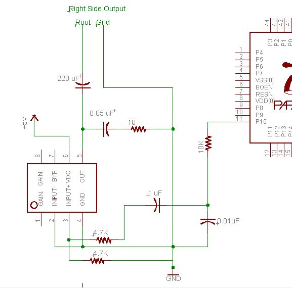
Attached is a schematic of the Audio amplifier that I just put together. I had done the same circuit awhile ago, but added the extra 4.7k resistor between the input and pin 3 of the LM386, and a second 4.7k pull down resistor from pin 3 and ground. The LM386 datasheet shows a 10k pot to adjust volume, I chose to use 2 4.7k resistors in it's place, to have a permanently fixed volume.
I thought the extra resistance would get rid of the distortion and clipping I was experiencing. Didn't help.
However, when I disconnect the wire between pin 2 ( -input ) and ground, the sound clears right up, and sounds good. What is going on here!
Another interesting twist. If I hold onto one end of a 4.7k resistor, and plug the other end into pin 3 of the lm386 as it's only input, I can hear a local AM radio station!!! I've had one of my children hold onto the resistor, with the same affect, so it's not just me. What is going on here???
▔▔▔▔▔▔▔▔▔▔▔▔▔▔▔▔▔▔▔▔▔▔▔▔
Brian Meade
"They who dream by day are cognizant of many things which escape those who dream only by night" - Edgar Poe
577 x 570 - 34K
Comments
Post Edited (TChapman) : 4/9/2007 1:26:24 AM GMT
WRT picking up AM broadcast stations, when you touch the input, your body is acting as an antenna and there is enough gain in the amplifier to rectify the local AM station and enable you to hear it.
Cheers, Ian
▔▔▔▔▔▔▔▔▔▔▔▔▔▔▔▔▔▔▔▔▔▔▔▔
Ian Mitchell
www.research.utas.edu.au
Post Edited (IanM) : 4/8/2007 11:28:50 PM GMT
A little more experimenting... I measured the voltage at the union between the 1 uF cap and the 4.7k resistor. I kept getting a negative voltage. I got the idea of connecting the center of the resistor voltage divider to "- input" instead of "+ input". I then connected "+ input" to ground. I now get good sound quality with this circuit with little or no clipping.
The question is... should I be getting a negative voltage from the RC filter? I don't have an o-scope to get a more accurate picture of what's going on.
I appreciate the feedback so far, but please, any other comments so that I might understand it better?
▔▔▔▔▔▔▔▔▔▔▔▔▔▔▔▔▔▔▔▔▔▔▔▔
Brian Meade
"They who dream by day are cognizant of many things which escape those who dream only by night" - Edgar Poe
Easiest change to make it clear: stick the pot back in where the pot should be. Play with the pot and you'll
understand. You're simply giving it way too much signal for the gain you've set.
I'd be happy leaving it that way, but I want to do it the "right" way, and I am going to have this made into a PCB.
▔▔▔▔▔▔▔▔▔▔▔▔▔▔▔▔▔▔▔▔▔▔▔▔
Brian Meade
"They who dream by day are cognizant of many things which escape those who dream only by night" - Edgar Poe
BTW, the LM386 isn't a very good choice. The Philips TDA7052 is much better, and uses fewer components.
Leon
I actually considered a TDA7053A(stereo), and I may switch to that chip for my final design. Problem is finding them. I see that you are from the UK, I originally heard about the TDA7052 and TDA7053A from a different forum, oddly enough, that forum is based in the UK, those chips must be more popular over on that side of the pond.
I normally order parts from both Mouser and Jameco, neither supplier has the TDA7053A, Jameco has the TDA7052, but the minimum order quantity is 2000
I just hate to walk away from this without solving the problem.
▔▔▔▔▔▔▔▔▔▔▔▔▔▔▔▔▔▔▔▔▔▔▔▔
Brian Meade
"They who dream by day are cognizant of many things which escape those who dream only by night" - Edgar Poe
If this is the case, I guess it's time to scope things. These LM386 circuits should be pretty foolproof.
▔▔▔▔▔▔▔▔▔▔▔▔▔▔▔▔▔▔▔▔▔▔▔▔
Brian Meade
"They who dream by day are cognizant of many things which escape those who dream only by night" - Edgar Poe
With power off, meter the + to GND and see what you get.
Post Edited (TChapman) : 4/10/2007 10:59:24 PM GMT
Freq.Synth("A",sPin,527)
waitcnt(20_000_000 + cnt)
Freq.Synth("A",sPin,0)
I'm not sure it's valid to call Freq.Synth("A",sPin,0) passing in 0 as the frequency. It definitely stops the sound, but a few seconds later I get some strange interference. Would it be better to set the sound pin to input when I want silence?
Thanks.
CP
Also the voltage supply varies with package, attention should be given with consideration to the part number in your hand. You may also need to include a decoupling capacitor to the input.
My opinion, opt for something with a 1%THD rating, it'll give alot cleaner sound, maybe even without the heat. The LM386 is good for a radioshack science project, not something production.
Hope this helps.
▔▔▔▔▔▔▔▔▔▔▔▔▔▔▔▔▔▔▔▔▔▔▔▔
E3 = Thought
http://folding.stanford.edu/·- Donating some CPU/GPU downtime just might lead to a cure for cancer! My team stats.
▔▔▔▔▔▔▔▔▔▔▔▔▔▔▔▔▔▔▔▔▔▔▔▔
E3 = Thought
http://folding.stanford.edu/·- Donating some CPU/GPU downtime just might lead to a cure for cancer! My team stats.