

help with dual rail power supply
 IanM
Posts: 40
IanM
Posts: 40
Hi guys,
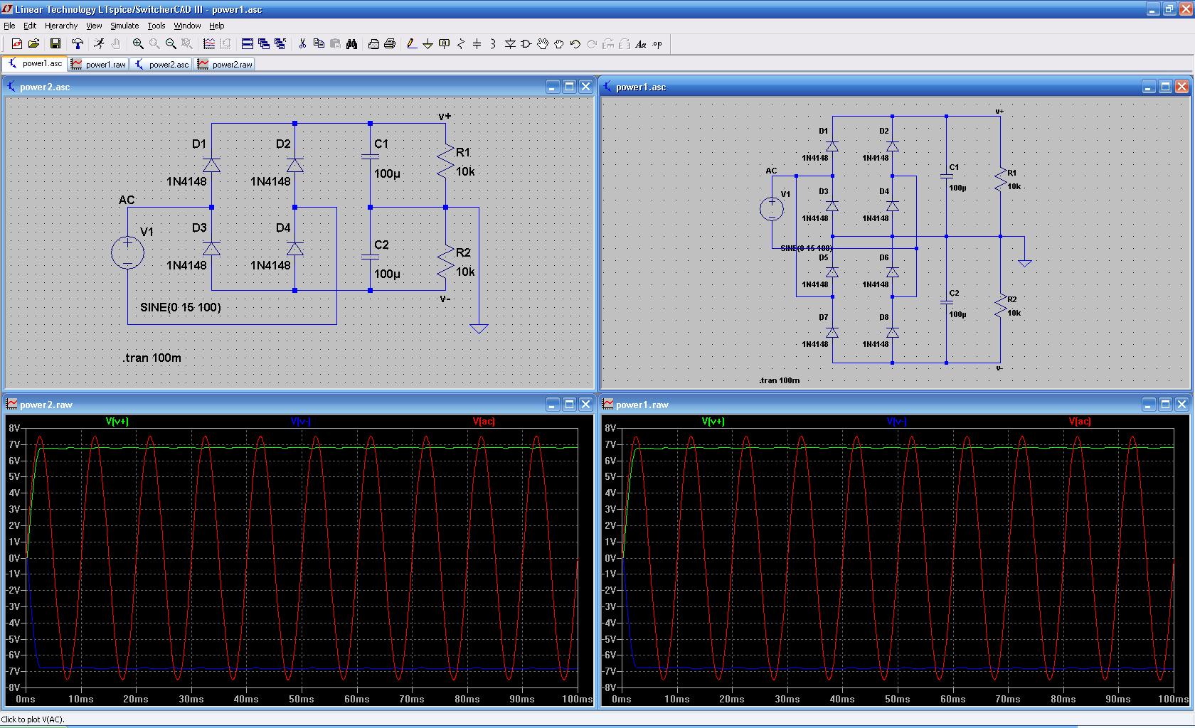
I'm trying to design a dual rail power supply using a single AC plug pack. The usual configuration consists of a full wave bridge rectifier with a center tap transformer - the tap being the earth return. I came up with a dual bridge rectifier to generate positive and negative voltages but then I wondered if it was possible to use a single bridge rectifier without a center tapped transformer?
I simulated both circuits and the results were identical. But, I can't help thinking it's not that simple. What is wrong with the single bridge circuit?
Please see attached, cheers, Ian
▔▔▔▔▔▔▔▔▔▔▔▔▔▔▔▔▔▔▔▔▔▔▔▔
Ian Mitchell
www.research.utas.edu.au
1680 x 1024 - 323K
Comments
What does work is to connect the AC voltage to the diode bride for the positive voltage drectly, but connect the AC voltage to the diode bridge for the negative voltage through two electrolytic capacitors (one in series with each AC lead), with the + sides of the elco connected to both terminals of the AC input voltage and the - terminals connected to the diode bridge.
The negative voltage will probably be loaded less than the positive voltage, so it's better to DC isolate the negative power supply than the more heavily loaded positive supply.
Using two 470µF elco's you can load the negative voltage with about 50...100mA
Mahjongg
Thats not a bad attempt assuming you're an electronics novice! The second circuit is functionally (almost) identical to the first because, as you can see, you have shorted the path between D3-D5 and between D4 -D6, so the diodes can be deleted from the circuit with no effect (unless the zero volt rail was to be pulled above or below the V+ and V- rails).
The main problem with your circuit is that you have created a common zero volt rail by dividing the DC output of the rectifier. This is fine as long as you don't want to draw any current from the zero volt rail. It has an effective impedance of 5K, so it is not a "solid" rail. The easiest way to create a good dual rail supply - as you suspected is to use a center tapped transformer. Hope that helps!
Cheers,
Shane.
Cheers, Ian
▔▔▔▔▔▔▔▔▔▔▔▔▔▔▔▔▔▔▔▔▔▔▔▔
Ian Mitchell
www.research.utas.edu.au
Another possible way is to use an of the shelf item like a DC DC converter module.
I have a datasheet attached to this post.
Very neat solution .. very efficient little switcher modules.. compact.. short circuit protected
Cheers
Ronald Nollet· Australia
Cheers,
Shane.
Check out this link http://www.discovercircuits.com/DJ-Circuits/splitsupply1.htm
The old discover circuit website its is pretty good for stuff like that and lots of other
goodies there as well.
Good nite from Melbourne Australia
Ronald Nollet
That link you just supplied caused me to nearly mess my pants in joy!!!!!
-Parsko
Later I want to build a prop based tunable version based on two props. The first programmed as a DDS driving the clock input of the second and using it's PLL and dividers to generate from about 1-120MHz. A 74act74 will divide by 4 to give an all band HF receiver.
Ronald - thanks for the circuit - looks like I got there eventually - cheers mate - and goodnight from sunny Tassie!
▔▔▔▔▔▔▔▔▔▔▔▔▔▔▔▔▔▔▔▔▔▔▔▔
Ian Mitchell
www.research.utas.edu.au
I suppose the textual description of my solution is a bit hard to follow, so I made a drawing.
Your "Power3" solution will only work with a tiny power load and is not useable in any practical circuit, unless you lower the 10K resistors much further, causing a massive power loss.
OzStamp's is the "classical" way to do it but only offers a "halve bridge" solution, which means that during halve of the AC periods the circuit is not fed, and you need very large elco's to feed the circuit during the other halve of the time (8 milli seconds of each 16ms or so at 60Hz AC) .
That means that this power supply is not very useable at higher supply currents.
My circuit however uses a full bridge for both the negative and the positive supply, and can deliver larger output currents, especially for the positive supply.
Mahjongg
▔▔▔▔▔▔▔▔▔▔▔▔▔▔▔▔▔▔▔▔▔▔▔▔
Ian Mitchell
www.research.utas.edu.au