

prop1 to control a VFD tube
 NNNN
Posts: 3
NNNN
Posts: 3
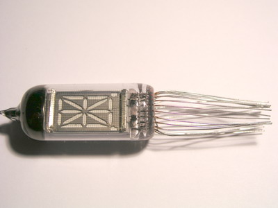
I have some old school vfd tubes... I also have a prop-1 chip, and I'm trying to figure out how to use it to control a number of tubes, maybe to do scrolling text or something like that. All I can think though is to use the 8 outputs to control 8 segments of one tube, but each tube has 16 segments (each lead coming off corresponds to a segment to light individually. Is there a more economical way? There's some french guy on the internet that's done it, but he's using a maxim ic driver and a 32 pin flash memory chip....and some other stuff. Not that I wouldn't be opposed to doing it that way, but I'm totally new to all this and wouldn't know how to put it all together. Any ideas?
thanks!
thanks!
Comments
Well, you are on the right track. As far as I know there are no Propellers in France.
I am a theory guy... when it comes to practical issues, I frequently ruin things. I think you are going to want to know what happens when you put 3.3 volts across any of those leads.
Then I think you are going to want to use a multiplexer... you will have to choose that before you can ask for any real help. Then you are going to need a circuit design of some sort so that the engineers don't blow a gasket. And then you should relate the whole thing to global warming to get the political support you deserve, but probably won't get without a little pandering.
None of this is intended to be sarcastic... if it sounds that way... it isn't.
I do try to entertain the guys at Parallax... but I wouldn't do it at your expense.
As you go along... please remember that there are a lot of people here who are trying to learn just as you are... such is me. And we would really like to get the full story and see all of the essentials.
Rich
You have the parts. Is there a part number anywhere on them? Have you a data sheet for them? Who made them? How old are they? Etc.
Some details would be helpful.
Depending on how many you want to use, it may be the Propeller can do that easily. I have a PIC driving 6 7-segment LEDs at about a 80 Hz rate (so each is ON about 1/6th of that period) and they are bright and usable.
Details, as much as you can supply...
▔▔▔▔▔▔▔▔▔▔▔▔▔▔▔▔▔▔▔▔▔▔▔▔
Harley Shanko
h.a.s. designn
It might be possible to use a shift register to control the pins, and perhaps some sort of transistor setup if it requires larger voltages than the propeller can provide.
Being vacuum devices you are bound to need quite a few volts to run them.
Graham
Back to the 'vacuum tube' days, eh?
▔▔▔▔▔▔▔▔▔▔▔▔▔▔▔▔▔▔▔▔▔▔▔▔
Harley Shanko
h.a.s. designn
There is a great forum for these types of tubes, with many folks who know them really well. Search for the Google group neonnixie.
Jonathan
▔▔▔▔▔▔▔▔▔▔▔▔▔▔▔▔▔▔▔▔▔▔▔▔
www.madlabs.info - Home of the Hydrogen Fuel Cell Robot
There used to be 74xx drivers that could handle the 100 - 200 V levels used to drive them. And, BTW, no filament in these. just raw field emission in a "rarefied" neon gas. Transistors like the BSW68 can be used - or little high-voltage mosfets. Always remember that a series resistor is needed - or you will short your HV supply. Not home now, will try and find a diagram later.
I looked into multiplexers. they look like they could be helpful, but I'm not entirely sure how to use them, as a 1 to 16 multiplexor must cover all possible scenarios for on and off, and then I'd be using 4 outputs (the one that gets split into 16, and 3 selectors). Is that right? would I need to manipulate one somehow (in term of ANDs and ORs) to get it to cover all possibilities, or do they come like that?
Any other ideas? thanks a ton!
The device appears to actually have 18 segments, if you intend to use the two 'decimal points' on each side at the bottom. So the code table will be quite wide to 'mark' the ON segments.
So the table will have 26 entries for letters, 10 for numbers, plus all the 'special' characters. 19 columns wide by at least 36 rows.
Appears you'll need a rather large look-up table or EPROM to drive the segments. And 'voltage translators' (3.3v from Prop to 25v to devices)
The mode the devices will be used (a register for each device, or a multiplexed drive directly from the Prop) will determine the other hardware and number of lines from the Prop.
Hopefully you can find documentation on your devices. Save lots of trial and error effort. Enjoy!
▔▔▔▔▔▔▔▔▔▔▔▔▔▔▔▔▔▔▔▔▔▔▔▔
Harley Shanko
h.a.s. designn