

Serial PIN expander
 willy1067
Posts: 107
willy1067
Posts: 107
previously known as theoretical 256 INPUT - OUTPUT BOARD
(I used Chris Savage clock circuit re-edited to my needs) http://forums.parallax.com/showthread.php?p=552892
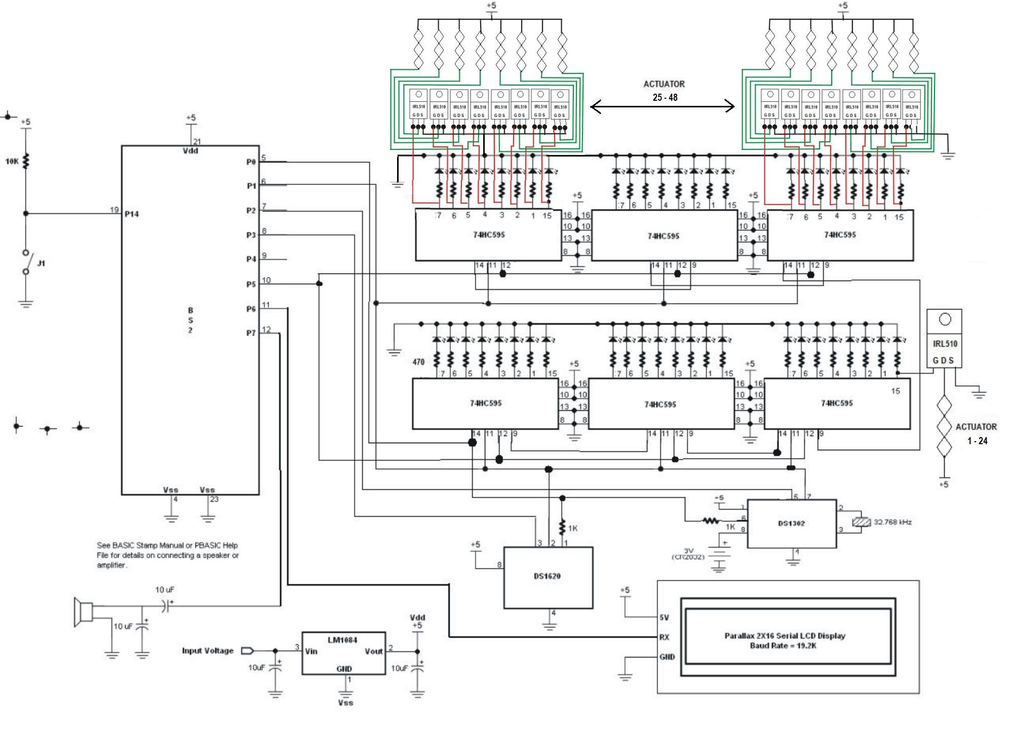
Decided to work on this project differently, to make the stamp control from 1 bit to as many needed serially. (this one controls 48 extra pins) controlled by·3 pins of the BS2.
So I have made a serial to parallel controller, controlling 48 LED's with 6 74HC595. (as experiment 23 from stamp work 2)
I will be using parallel to serial chips to input to the BS2, as experiment #24; and together make it as experiment #25. Controlling a total of 48 input and 48 outputs.
(I am not a programmer, so I will need help on that area)
Lets put this together... great project don't you think?·· Imagine the uses of this.
other projects;
·http://forums.parallax.com/showthread.php?p=637017·) Human robotic hand
·http://forums.parallax.com/showthread.php?p=641371·= $10 Stepper motor Controller
·http://forums.parallax.com/showthread.php?p=656332·= CNC project
Post Edited (willy1067) : 12/22/2007 1:41:53 PM GMT
(I used Chris Savage clock circuit re-edited to my needs) http://forums.parallax.com/showthread.php?p=552892
Decided to work on this project differently, to make the stamp control from 1 bit to as many needed serially. (this one controls 48 extra pins) controlled by·3 pins of the BS2.
So I have made a serial to parallel controller, controlling 48 LED's with 6 74HC595. (as experiment 23 from stamp work 2)
I will be using parallel to serial chips to input to the BS2, as experiment #24; and together make it as experiment #25. Controlling a total of 48 input and 48 outputs.
(I am not a programmer, so I will need help on that area)
Lets put this together... great project don't you think?·· Imagine the uses of this.
other projects;
·http://forums.parallax.com/showthread.php?p=637017·) Human robotic hand
·http://forums.parallax.com/showthread.php?p=641371·= $10 Stepper motor Controller
·http://forums.parallax.com/showthread.php?p=656332·= CNC project
Post Edited (willy1067) : 12/22/2007 1:41:53 PM GMT


Comments
You can also dumb it down a little and use 4 MAX7219 controllers. I have had success using them with a 8x8 led matrix. You can also get them as samples. Just make sure to use a resistor for the Iset pin or else you roast the chip itself. I roasted about 10 thinking I was doing something else wrong and then I realized I was using the wrong resistor.
Good luck,
Engin
www.maxim-ic.com/quick_view2.cfm/qv_pk/3410
There are quite a few ways to go. It is not 100% clear what you goal is. 1 LEd at a time only, or the possibility of all 1-256 on?
I wold think a matrix using I2C, like the 16bit PCF8575 would be easy to do. It may be an easy solution to use 2 PCF8575's, one turns on 16 transistors for the high side of the matrix. 1 turns on the low side bus. I'll draw something in a sec.
Post Edited (TChapman) : 3/29/2007 8:28:48 PM GMT
If you don't have much experience, then order some max7219 samples (16 of them) and while you wait to receive them do a search for max7219 and find some code on this forum.
https://shop.maxim-ic.com/storefront/searchsample.do?event=Sample&menuitem=Sample&Partnumber=MAX7219CNG+
good luck.
Engin
It would cost you 2 PCF8575's, 16 optos(or 4 quads)
To send %1111_1111 to get LED #256 on, it would require a lookup or other trick to convert number 256 to TWO I2C devices. Someone else may know a neat trick to convert it.
To turn on the LOW side device, a LOW or 0 is required at it's output, otherwise it stays high for LED = OFF.
To turn on the HIGH side output, a HIGH output is required, as the pullup shown on the opto input is the source for the opto LED, which in turn turns on the HIGH Rail for that bus.
**This circuit is just an idea, there are obvious flaws for purposes of turning on ALL the leds on a bank of 16--- the opto used for switching the high side would have to be able to source 16 LEDs at 15-20ma. This may be doable depending on the opto, an appropriate power rated transistor could work as well.**
Oh and both 8575's need their own unique address, like %000 and %001. I drew them the same address
Post Edited (TChapman) : 3/30/2007 9:21:33 AM GMT
I have also built an 7x20 LED display that I used with either a BS2 or SX28 and some 4017 decade counters to display scrolling messages.
If you don't need all the LEDs on at a time then what I posted is fine.
If you do want all on as a possibility, a transistor per LED on the high side is a lot of parts, but there are 8 channel arrays that would reduce the part count to 256/8 for the transistor arrays.
Post Edited (TChapman) : 3/30/2007 2:36:51 AM GMT
Let me explain my use for this board at this time, and remember this will be use for much more.
At power up of my ROBOTIC ARM DESIGN, this logic has to be followed;
I will use the term PORT instead of LED's because each theoretical LED is been used as Input/Output.
1. Power up - set all I/O to 0. (to prevent any joint movement, turn all Ports off)
2. sense limit switches (detect each joint location, Here I will need 20 of the Ports to act as analog to digital)
3. move all joints home (here I will need 20 of those Ports ON, but instead of LED's I will drive transistors to move the Gears forward.
3. Query - are all joints at home? if not continue moving all necessary ports ON, turn off those that are home.
4. check temperature sensors (about 20, thru out the hand) send value to memory address assigned for temperature values.
5. check touch sensors (about 20, " " " " .....)
6. check vibration sensors (about 6, " " ......)
7. receive movement commands and continue obtaining temperature, touch and vibration values
as you can see, I will need 40 ports to control 20 fingers joints, 20 analog to digital for positioning. and 46 for for reading sensors values.
total 106 as of now needed.
I am sure this is mind boggling, but when I started this project, I said the same thing about the gears, the computer, then the stepper motor controller, but at each step of the way I continue moving forward. The gears are done, I found the BS2, the stepper motor is moving. now it's just another challenge.
If anyone has a better solution to my problem, solutions are welcomed.
▔▔▔▔▔▔▔▔▔▔▔▔▔▔▔▔▔▔▔▔▔▔▔▔
Fernando Gomez
revinc.us
gomez-rivera.com
Never compare yourself with anyone else, there will always be someone bigger·or·smaller·than you.
It is not really clear what you mean by "theoretical LED is being used as an input/output". The 257 LEDs could be managed by only 2 pins though.
digikey.com for the PCF8575 is 296-17792-1-ND smt only
On the low side but you can use the ULN2803, it is 8 channels and each channel will sink 600mA, so use one channel per bus, two IC's required for the low side. Also, the 8575 will have to have 4.7k -10k pullups in front of the ULN input to turn it on properly for the 2803's.
Any suggestions welcome from others that really know this stuff.
***Here is an updated version with PNP mosfets on top*** Keep in mind, there could easily be better methods, this is just a fun exercise for something I may use in the future.
Post Edited (TChapman) : 3/30/2007 8:46:30 PM GMT
Here is the 20 column x 7 row moving LED display sign I built for the SX28. I originally built it for the BS2 (but it is a little bit slower - but faster with a BS2px or SX28 version). There is also a link for the BS2 version with code for both. It requires either a BS2, BS2px, or SX28 and 3 4017 decade counter chips and a 4081 AND gates. It's a fun project to build but you can only scroll in 1 direction (right to left is best - or I guess it can be modified to just·animate single words that fit on the 20 column display.
http://forums.parallax.com/showthread.php?p=561515
I also have a 16x16 LED display as mentioned before but it uses an interupt routine (written mainly by JonnyMac). The LED circuit schematics are basically the same as the 20x7 LED display (just 16 columns by 16 rows). You can also use ULN2803 (8 outputs each) to drive the columns. The rows can be 2N3906 PNP transistors or any higher current driving PNP transistor. The rows need negative inputs to the transistor· / resistor circuits into the Anode LED rows. The column rows need positive inputs into the (2) ULN2803's chips which privide negative inputs into the cathode LED columns.
This means you will need 16 negative inputs for the rows and 16 positive inputs for the columns. It could have been done serially·with 3 wires·on (2) 74HC595's for the rows and 3 wires on (2) additional 74HC595's AND (3) invertors such as 74HC04's. This would go to the column ULN2803 chips. This would only require 6 Input lines on a microcontroller. However, I think the programming would be much more difficuilt.
I choose instead to use an SX52 (although an SX48 could have been used). Parallex sells the protoboards for $10 (you will need only of their wall transformers to power it ($8). However, if you use the SX chips you will need a $30-$50 SX Blitz or SX Key programmer device. I think it is worth it.
Here is a link to some of the code development I worked on with JonnyMac for the SX52. It has the code that you can look at in any text program like Notepad. I have even gone farther using the RobOympic routine to read and scroll messages out of DATA statements in this code I beleive. It has 2 pages of postings.
http://forums.parallax.com/showthread.php?p=636887
Let me know if I can help you any further or answer any questions. No problem.
Have fun.
Post Edited (T&E Engineer) : 3/31/2007 12:55:51 AM GMT
and the reason I pick that device instead of the ones posted here, is because each LED can be controlled individually, no scrolling involved.
I will order it, and see how it works, this will work great as the Output and LED's driver.·· now·I just need the INPUT side of it.
·http://www.vellemanusa.com/images/products/0/vm112_fish-animation.gif
anyone have an idea on how to obtain an analog value from an array?
▔▔▔▔▔▔▔▔▔▔▔▔▔▔▔▔▔▔▔▔▔▔▔▔
Fernando Gomez
revinc.us
gomez-rivera.com
Never compare yourself with anyone else, there will always be someone bigger·or·smaller·than you.
Post Edited (willy1067) : 3/31/2007 3:07:15 AM GMT
Below is a link to a "slider" touch sensor. Maybe it can be used somehow for input, as it will output values as you move your finger along a touch sensitive path.
www.qprox.com/downloads/datasheets/qt411_issg-601.pdf
I've got 3 or 4 of the PCA9554 that I probably bought from DigiKey some time ago. I've not used them with a Stamp although they should work fine. I have one on my Propeller BOE-BOT that I'm using to run an HM55B compass and soon a Hitachi 3-axis accelerometer.
I use 3 different vendors for electronics parts: Digikey, Jameco, and Mouser. They all have webstores, accept small orders, have good service, reasonable prices, and a wide variety of parts.
Check out the Nuts and Volts columns by Jon Williams. You can get to them via the Downloads menu item on Parallax's main webpage. There are several columns on using I2C devices, particularly I/O expanders. You will also need the datasheet from the NXP Semiconductors website (www.nxp.com).
the company also make other chips, like
PCA6971 and PCF8575
Question, is there any difference between them?
http://www.nxp.com/products/interface_control/i2c/index.html
▔▔▔▔▔▔▔▔▔▔▔▔▔▔▔▔▔▔▔▔▔▔▔▔
Fernando Gomez
revinc.us
gomez-rivera.com
Never compare yourself with anyone else, there will always be someone bigger·or·smaller·than you.
The LED badge looks cute, but you won't get any input from the display. Please have a look at this website for information on using LEDs as input devices: projects.dimension-x.net/technology-and-projects/ledsensors/.
So I have made a serial to parallel controller, controlling 48 LED's with 6 74HC595. (as experiment 23 from stamp work 2)
I will be using parallel to serial chips to input to the BS2, as experiment #24; and together make it as experiment #25. Controlling a total of 48 input and 48 outputs.
controlled by 4 pins of the BS2.
▔▔▔▔▔▔▔▔▔▔▔▔▔▔▔▔▔▔▔▔▔▔▔▔
Fernando Gomez
Never compare yourself with anyone else, there will always be someone bigger·or·smaller·than you.
▔▔▔▔▔▔▔▔▔▔▔▔▔▔▔▔▔▔▔▔▔▔▔▔
Fernando Gomez
Never compare yourself with anyone else, there will always be someone bigger·or·smaller·than you.
There are two programs for project 23 of the StampWorksCode2.1;
If I use program 1, I get all 6 74HC595 to work as one(1). repeating the same code every 8 LEDs.
If I use program 2, I get 3 sets of code repeating every 16 LEDs. (works as if there are two 595's)
What do I change to let the program know there are (6) 595's IC?
▔▔▔▔▔▔▔▔▔▔▔▔▔▔▔▔▔▔▔▔▔▔▔▔
Fernando Gomez
Never compare yourself with anyone else, there will always be someone bigger·or·smaller·than you.
"When cascading multiple shift registers, you must send the data for the device that is furthest down
the chain first. Subsequent SHIFTOUT sequences will "push" the data through each register until the
data is loaded into the correct device. Applying the latch pulse at that point causes the new data in
all shift registers to appear at the outputs."
I would assume that if you wanted to access say the 4th 595, you will need 3 shiftouts to push the data from the 6th 595 to the 4th. So to put data on the first, you would need 6 shiftouts. After all data is loaded then the latch is applied.
I think you will have to play around with this to see how it actually works. You could make shiftout subroutines for each 595 to save you the coding.
▔▔▔▔▔▔▔▔▔▔▔▔▔▔▔▔▔▔▔▔▔▔▔▔
Fernando Gomez
Never compare yourself with anyone else, there will always be someone bigger·or·smaller·than you.
Not sure how I missed it before…But I got looking at your schematic and it looks very familiar…It looks as if you modified the one found here…
http://forums.parallax.com/showthread.php?p=552892
(I see you mentioned that in your first post...but I came into this one late...)
▔▔▔▔▔▔▔▔▔▔▔▔▔▔▔▔▔▔▔▔▔▔▔▔
Chris Savage
Parallax Tech Support
not to use it for something else.
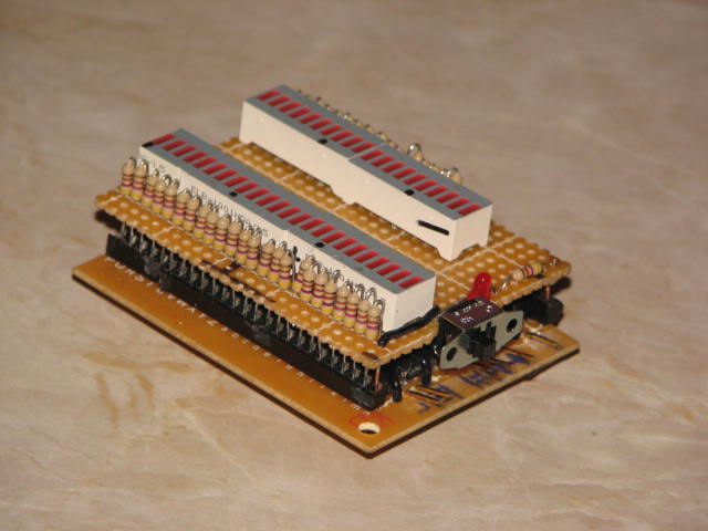
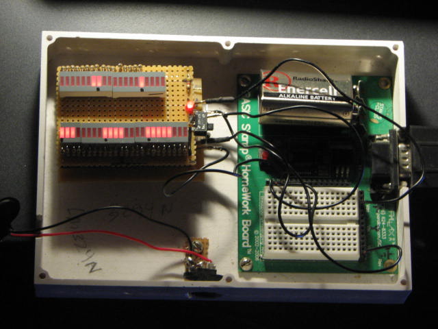
I did program the circuit last night and it works, I am able to send 6 shift out values, and they activate the various bits, I will post a new picture and few short lines of code for it tonight
Post Edited (willy1067) : 12/20/2007 3:13:59 PM GMT
'{$PBASIC 2.5}
'This bit of code tests (6)74HC595 shift registers.· First bit out goes to QH of the first 595,
'then shifted to the next 595, until it reaches the last 595 connected to the row.
dat PIN 1········· '595.14
clk PIN 0·········· '595.11
latch PIN 2······· '595.12··· 595.10 to Vdd·· 595.13· ground
···················· · '595.9 TO 14 from first to last
start:
'This first program sends a 00000001 to the last shift register of the first 595.· We
'are using LSBFIRST, which means that the least significant bit is shifted out first.
'The first Bit shifted out goes to pin Qh, the second bit to Qg, the third bit to Qf,
'and so on.· We want to make pin Qh high so it will turn on the Darlington connected to it.
'Pin 9 of first 595 shifts the next 8 bits to pin 14 of the second 595 and pin 9 of second
'595 in turn keeps shifting to the following 595.
LOW latch
SHIFTOUT dat, clk, LSBFIRST, [noparse][[/noparse]1] '1 same as %00000001
PULSOUT latch, 5············ 'sends a pulse 5ms wide to the latch line
LOW latch
SHIFTOUT dat, clk, LSBFIRST, [noparse][[/noparse]3] '3 same as %00000011
PULSOUT latch, 5
LOW latch
SHIFTOUT dat, clk, LSBFIRST, [noparse][[/noparse]7] '7 same as %00000111
PULSOUT latch, 5
LOW latch
SHIFTOUT dat, clk, LSBFIRST, [noparse][[/noparse]15] '15 same as %0001111
PULSOUT latch, 5
LOW latch
SHIFTOUT dat, clk, LSBFIRST, [noparse][[/noparse]31] '31 same as %00111111
PULSOUT latch, 5
LOW latch
SHIFTOUT dat, clk, LSBFIRST, [noparse][[/noparse]63] '63 same as %01111111
PULSOUT latch, 5
LOW latch
Post Edited (willy1067) : 12/20/2007 3:17:14 PM GMT
Looking at your code, if you have the 595's wired up so the latches are being shared by the same stamp output pin, you should only need to apply it once after all the shiftouts. At least this is the way i figure it should work according to the way it is explained.
Chris also posted a line of code, that I will try tonigh.
SHIFTIN SerData, Clock, MSBPRE, [noparse][[/noparse]value1, value2, value3, value4, value5]
Thanks guys, for all the input
▔▔▔▔▔▔▔▔▔▔▔▔▔▔▔▔▔▔▔▔▔▔▔▔
Fernando Gomez
Never compare yourself with anyone else, there will always be someone bigger·or·smaller·than you.
'{$STAMP BS2}
'{$PBASIC 2.5}
dat PIN 1
clk PIN 0
latch PIN 2
start:
LOW latch
SHIFTOUT dat, clk, LSBFIRST, [noparse][[/noparse]1, 3, 7, 15, 31, 63]
PULSOUT latch, 5
LOW latch
Post Edited (willy1067) : 12/24/2007 1:05:23 AM GMT
good luck guys, enjoy this great project; and put it to good use.
Question...· How Can I move this to the Completed Projects Forum?
Post Edited (willy1067) : 10/11/2008 6:42:13 PM GMT