

Energy Efficient Supplies
 T Chap
Posts: 4,260
T Chap
Posts: 4,260
Some thinking out loud on an EE supply design.
I have around 8 boards that have both 5vdc and 3.3VDC regulators on them. There is also a DC motor driver board that needs to provide 32-38 VDC at 3-4 amps when the motor is used. When the motor is not used, it does not require holding torque, the encoder will detect any error and pull it back in place if required.
I am looking for the most energy efficient way to supply the system, I am thinking 1.5 amps will be the ballpark for the logic boards when I am done, and 7-10VDC will power all the regulators. I intend to use a toroidal for the motors if I can find one beefy enough, 24VAC will get me the required unregulated ~37DC. The question is, will using another smaller 6VAC transformer be the most economical to produce the ~10VDC for the logic supply? Wouln't regulating down the 24VAC burn a lot more juice that just adding a smaller transformer?
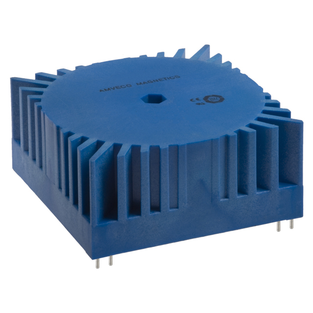
Looking at the Amveco Toroidals, they claim "low no-load current and very low no-load losses." I had considered using a really large cap on the motor driver, and switching out the large Xformer when not in use(no idea yet on where or how to switch it. The big cap just needs to provide a few milliseconds of power if the motor is required to do some work(motor is off more than on).
There could be a Prop ADC monitoring the cap, if it drops below some usable value, it kicks the 24VAC>Bridge rect back in, fills back up the cap and shuts off again. This idea is strictly to reduce power consumption. If the transformers really didn't pull anything when idle, maybe not even bother with the switching idea. The logic supply AC source is the real question.
Any sugggestions on these ideas?
Post Edited (TChapman) : 3/28/2007 3:53:46 AM GMT
I have around 8 boards that have both 5vdc and 3.3VDC regulators on them. There is also a DC motor driver board that needs to provide 32-38 VDC at 3-4 amps when the motor is used. When the motor is not used, it does not require holding torque, the encoder will detect any error and pull it back in place if required.
I am looking for the most energy efficient way to supply the system, I am thinking 1.5 amps will be the ballpark for the logic boards when I am done, and 7-10VDC will power all the regulators. I intend to use a toroidal for the motors if I can find one beefy enough, 24VAC will get me the required unregulated ~37DC. The question is, will using another smaller 6VAC transformer be the most economical to produce the ~10VDC for the logic supply? Wouln't regulating down the 24VAC burn a lot more juice that just adding a smaller transformer?
Looking at the Amveco Toroidals, they claim "low no-load current and very low no-load losses." I had considered using a really large cap on the motor driver, and switching out the large Xformer when not in use(no idea yet on where or how to switch it. The big cap just needs to provide a few milliseconds of power if the motor is required to do some work(motor is off more than on).
There could be a Prop ADC monitoring the cap, if it drops below some usable value, it kicks the 24VAC>Bridge rect back in, fills back up the cap and shuts off again. This idea is strictly to reduce power consumption. If the transformers really didn't pull anything when idle, maybe not even bother with the switching idea. The logic supply AC source is the real question.
Any sugggestions on these ideas?
Post Edited (TChapman) : 3/28/2007 3:53:46 AM GMT
640 x 640 - 172K
Comments
I will have a look at best rated trafo's ...
In the meantime - I have attached a datasheet on the LT1074
▔▔▔▔▔▔▔▔▔▔▔▔▔▔▔▔▔▔▔▔▔▔▔▔
'Necessity is the mother of invention'
I remember some cheap 24VAC CT 4amp transformers I got from Allelectronics recently(photo), they were pretty warm with no load, then again probably not very efficient.
I like the asthetic of the blue Amveco, but the largest PCB mount they show is 22VAC, 2.28 amps, maybe could be sufficient for the task.
Post Edited (TChapman) : 3/28/2007 4:21:33 AM GMT
www.plitron.com/
▔▔▔▔▔▔▔▔▔▔▔▔▔▔▔▔▔▔▔▔▔▔▔▔
'Necessity is the mother of invention'
or use 2 x lt1074's (1 for 3.3v the other for 5v ) as the range is from 2.5VDC to 60VDC with high output current capabilities as per datasheet.
Option1 - Use 1xLT1076-5 and 1xLT1074 (set to 3.3v)
Option2 - Use 2xLT1074 - (1 for 5V) the other (3.3v)..
these are all short circuit protected.
·- the 7pin package has Current limiting option - so you can limit the Imax out from the reg - so you don't cook the trafo..
▔▔▔▔▔▔▔▔▔▔▔▔▔▔▔▔▔▔▔▔▔▔▔▔
'Necessity is the mother of invention'
Post Edited (QuattroRS4) : 3/28/2007 4:26:10 AM GMT
A complete switched mode power supply with multiple outputs ...
look at VLT40-3203 in the datasheet
▔▔▔▔▔▔▔▔▔▔▔▔▔▔▔▔▔▔▔▔▔▔▔▔
'Necessity is the mother of invention'
Post Edited (QuattroRS4) : 3/28/2007 4:43:18 AM GMT
www.allelectronics.com/cgi-bin/item/PS-115/480/130_WATT_SWITCHING_POWER_SUPPLY_.html
Something similar above, 5V/5A, 24V/5A for $37. I can test the motors on the 24V rail and check the performance(BLDC). Since I already have the 5VLDOs>3v3LDOS on the boards, I may be able to get away with feeding them the 5V switched supply. I need to check where the drop out is, but I would think you could put 5 in and still get 5 out. That would be very effecient if it worked. This is new territory for me so forgive the ignorance on the subject. The real issue may be if there is no load on the 24V, will the supply stay happy.
It's nice that All electronices is <10 miles away, I know the guys there pretty well, I'll just plug it in on the counter and test it out.
▔▔▔▔▔▔▔▔▔▔▔▔▔▔▔▔▔▔▔▔▔▔▔▔
'Necessity is the mother of invention'
What about I make a board that can be stacked with board offsets, build one that outputs 36V with the LT 1024 on it, and see how it goes with the motor. If I can't gear it enough to get the work done, then stack another 2.2 amp transformer>rectifier>cap on top of the other board and parallel the outputs?
Post Edited (TChapman) : 3/31/2007 7:50:46 AM GMT
▔▔▔▔▔▔▔▔▔▔▔▔▔▔▔▔▔▔▔▔▔▔▔▔
'Necessity is the mother of invention'
Post Edited (TChapman) : 4/1/2007 4:19:51 AM GMT
That is looking sweet !
▔▔▔▔▔▔▔▔▔▔▔▔▔▔▔▔▔▔▔▔▔▔▔▔
'Necessity is the mother of invention'
Great looking schematic and board ..
The only comment I have is that the track with the 5VDC on it seems a little narrow..
It of course depends on how much current you draw from this PSU but I would receommend
you fatten the tracks slightly.
Rgds
Ronald Nollet Australia