How to read a Heart Rate sensor
So now I've got the sensor. So how do I read it?
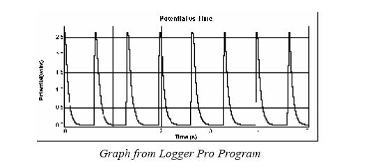
This is a heart rate monitor sensor. A graph of the sensor's out put is attached to this posting.
Their specs state that it runs at 5v, 30 - 55 uA. Output is either 5V or 10V... I'm not sure which.
I don't have a oscilloscope.
I plan to try just putting the output into a BS2 input pin and seeing if the COUNT command will work.
What sort of filtering or conditioning might I do on this device?
I was thinking maybe the ADC described in chapter 3 of the Process Control course www.parallax.com/dl/docs/prod/sic/Web-PC-v1.0.pdf might provide the ability to adjust the threshold down a bit, where the spike from the sensor is wider. But, I really have no idea what I'm doing.
I'd welcome any suggestions.
Thanks!!
Post Edited (Tom F) : 3/24/2007 6:52:52 PM GMT


Comments
This should really stay in the original thread, or at least have an equally descriptive subject re the Heart rate monitor.
The graph looks like the signal will be a fine match to the Stamp. It peaks up to 2.5 volts, which is above the Stamp input threshold of ~1.4 volts. Connect the signal via a resistor of around 1kohm (just a safety precaution) to a Stamp input pin. Connect the commons.
Then you have a variety of Stamp commands to choose from. The signal is fairly slow, so you can start with a simple pin monitor:
That simply streams the readings of the pin state (pin p0) to the debug screen.
Then you can try
COUNT 0,10000,result
as you know to count pulses for 10 seconds. There are other methods to measure the time, too, if, say, an you want an update of time between each beat, instead of waiting for 10 seconds for each update.
▔▔▔▔▔▔▔▔▔▔▔▔▔▔▔▔▔▔▔▔▔▔▔▔
Tracy Allen
www.emesystems.com
Reading the pin with this code:
DEBUG BIN1 in0
results in nice looking data in StampPlot. (See attached HR-Bin1) My heart is between 50 and 60 beats per minute, about one beat per second (as shown on the HR watch I'm wearing.) The plot shows that.
However, if I use COUNT 0, 10000, Result, the results are not what I'd expected (See attached HR-Count1). The ten second sample period is 1/6 of a minute, so I expected values from a ten second sample to be approximately 1/6 of 50 to 60, or 9 or 10. However, as the plot shows, the values are twice that!
And, the values show a surprising variability. I figured that a ten second period for the count would result in more consistent results, differing by one or two counts intermittently.
Any suggestions?
PS I changed the subject of this thread to indicate it's a heart rate sensor discussion. And my apologies for starting a new thread. I know it's bad forum etiquette... but I figured that the original thread was a bit chatty and so had probably lost some readers. And, we were beyond the "What sensor should I use?" discussion, into the "How to make it work?" discussion, a new thread could be appropriate...