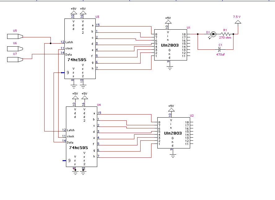
ULN 2803 and Shift Register
Hi All,
Could someone take a look at this schematic that I am using to drive some leds?
I am not sure what voltage should go to the 2803 - should the uln2803 have 5v to pin 10, the same 5v that goes to the shift register and then all grounds tied together? Or should it get the 7.5 volts that are driving the leds with the grounds tied together?
It seems to work the way it have it, but if I take off the 5v to the 2803 - the leds still light but don't go off all the way...
I just wonder if someone could check my work as I am unsure about the power connections, despite having looked at the data sheet...
Thank You!
Carlos Ferguson


Comments
Post Edited (originator) : 3/22/2007 6:29:53 AM GMT
Reading your post I get the sense that the 5v to pin 10 might be a problem? I don't need anything on this pin? - or should I instead tie it to the 7.5 that powers the leds? All grounds should be tied together as a general rule?
The ULN's are actually driving 16 leds, I just didn't want to draw them all in...
Anyway, it SEEMS to work right as drawn in that circuit, but I am just unsure of the pin 10 connection...
Thanks,
Carlos
Post Edited (originator) : 3/22/2007 6:54:43 AM GMT
I will let pin 10 float then...
the uln2803 sinks current to the output pins when it is brought high on the input pin ( I think ). So wouldn't I want a pull-down resistor on the inputs to make sure it goes off all the way? I'm not sure this is necessary but I just want to understand why.
Carlos
I am not very familiar with the 595, but you may need to check what state it is in when you want the LEDs off, it may be that the IC is floating when you want the IC off, which may account for the ULN not fully turning off the LED. Just for a test, look at an LED that is staying partially on, pull down that channel ULN input with a jumper to GND, see if it kills the LED. If it does, try a 10k, or 4.7k as pulldown. I think you should test it without the 470 to see if it goes out completely, as it doesn't really add up yet what is causing the LED to stay on..
Post Edited (originator) : 3/22/2007 8:33:34 PM GMT
Carlos