No Interupt pin
·
· I’m designing a robot that will roam towards a bright light in a room and at the same time be able to avoid obstacles in its path. I would also like to design the robot to be able to hear a sound from a piezo buzzer and interrupt whatever routine it was performing and jump to another routine. Would this be possible since the Basic Stamp II doesn’t have an interrupt pin like other microprocessors do?
·
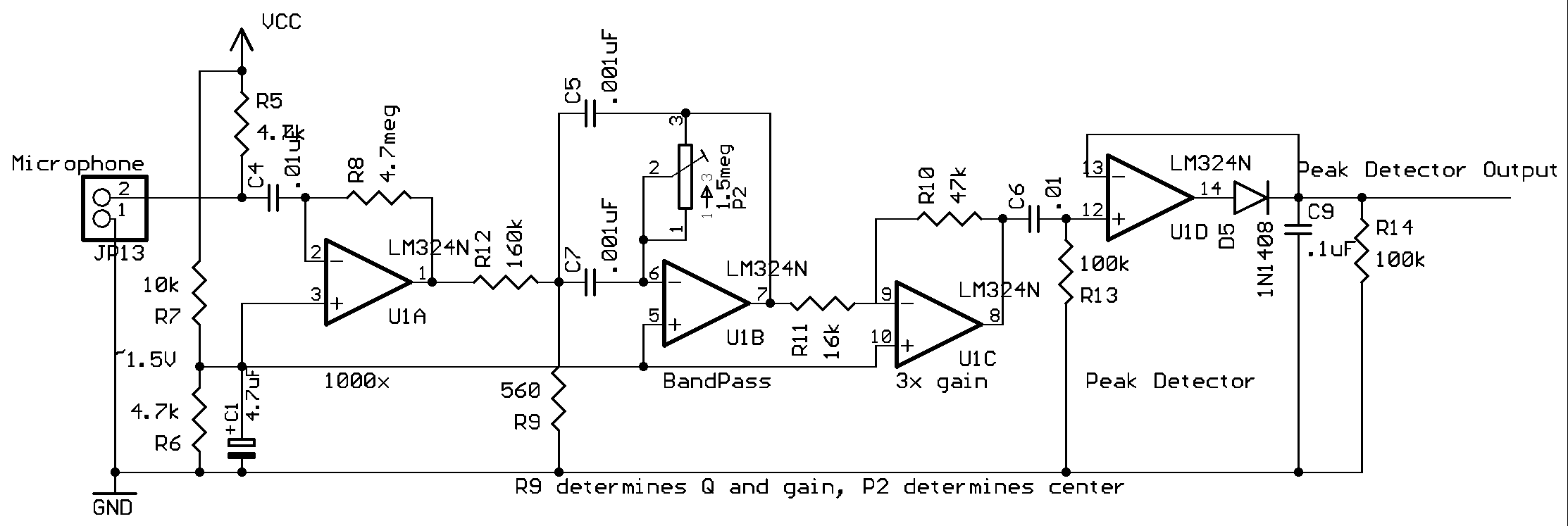
Also does anyone have a good audio detection circuit? I found the one below online and I think it should work. I know this may seem like a stupid question but, the polarity and type of capacitors in this circuit wouldn’t make a difference, would it? It seems like a very popular circuit because I’ve seem it on many robot designs. If anyone has used it could you please give me some feedback on it?
·
·

PDF version of the schematic
·
·
·
·
·
· I’m designing a robot that will roam towards a bright light in a room and at the same time be able to avoid obstacles in its path. I would also like to design the robot to be able to hear a sound from a piezo buzzer and interrupt whatever routine it was performing and jump to another routine. Would this be possible since the Basic Stamp II doesn’t have an interrupt pin like other microprocessors do?
·
Also does anyone have a good audio detection circuit? I found the one below online and I think it should work. I know this may seem like a stupid question but, the polarity and type of capacitors in this circuit wouldn’t make a difference, would it? It seems like a very popular circuit because I’ve seem it on many robot designs. If anyone has used it could you please give me some feedback on it?
·
·

PDF version of the schematic
·
·
·
·
·


Comments
will react to it.
Without intending to discourage, let me mention that lacking an interrupt the motors will have to stop to evaluate light levels, then again (or longer) to check the bump sensors, then again (or longer) to check the tone sensor. This is fine for experimental use and most hobbyists (me included) are happy just to see their creation move, but the lag can get noticeable to the point of bothersome when the sensor load gets heavy.
The audio circuit you posted outputs between 1000 and 2000 pulses per second (presumably, to drive a servo directly it would have to). Depending on the resolution you require (1 command tone? 10 command tones? 100?) you may have to listen for 1/100th of a second? 1/10th of a second? 1/2 a second?) or sample several times to get accurate interpretation of the input tone frequency; processors work fast, but not always efficiently. As to the capacitor polarity—I see only one (C1), probably electrolytic, marked clearly with a ‘+’. For the others use non-polarized and worry not! Just remember to keep your capacitor voltage rating at least twice the voltage applied.
My advice? Try it! Even if it doesn't work as expected, you'll learn alot trying and, hopefully, enjoy the experience!