

Poor Man's Demo Board
 parts-man73
Posts: 830
parts-man73
Posts: 830
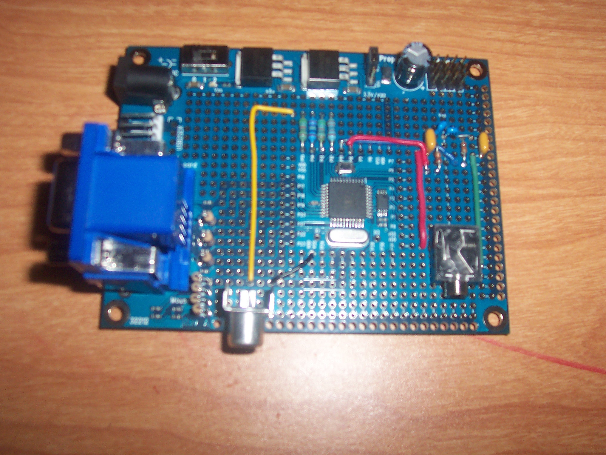
There was an earlier thread where I had brought up a little project I had going on with one of the new Proto Boards. I called it the Poor Man's Demo Board.
Over the weekend I managed to finish the audio jack. and here are some pictures, and well as a schematic of the audio section.
I had tried for awhile to use a couple of LM386 to amplify the output of the Prop. But all I got was horrible distortion and clipping. When I get a chance, I will post the circuit I was trying so that you can pick it apart and tell me where the problem lies.
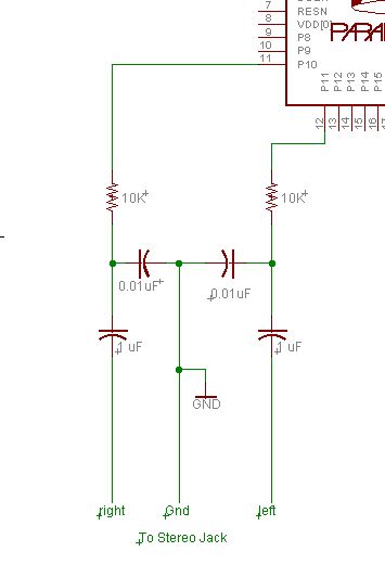
For now, I have it set up like the second image attached. When my amplified speakers that I use with my computer are connected, I get very nice, distortion free sound.
So now I have connections for VGA, Mouse, Keyboard, Composite Video, and Stereo Sound. The sound only works with amplified speakers though. There's no Mic like the demo board, but I don't have anything planned that uses the mic, so I'll keep those 2 IO's open for future use. I'll solder on a female header for quick connection to P0-P7.
▔▔▔▔▔▔▔▔▔▔▔▔▔▔▔▔▔▔▔▔▔▔▔▔
Brian Meade
"They who dream by day are cognizant of many things which escape those who dream only by night" - Edgar Poe
Over the weekend I managed to finish the audio jack. and here are some pictures, and well as a schematic of the audio section.
I had tried for awhile to use a couple of LM386 to amplify the output of the Prop. But all I got was horrible distortion and clipping. When I get a chance, I will post the circuit I was trying so that you can pick it apart and tell me where the problem lies.
For now, I have it set up like the second image attached. When my amplified speakers that I use with my computer are connected, I get very nice, distortion free sound.
So now I have connections for VGA, Mouse, Keyboard, Composite Video, and Stereo Sound. The sound only works with amplified speakers though. There's no Mic like the demo board, but I don't have anything planned that uses the mic, so I'll keep those 2 IO's open for future use. I'll solder on a female header for quick connection to P0-P7.
▔▔▔▔▔▔▔▔▔▔▔▔▔▔▔▔▔▔▔▔▔▔▔▔
Brian Meade
"They who dream by day are cognizant of many things which escape those who dream only by night" - Edgar Poe
2032 x 1524 - 708K
355 x 532 - 17K
Comments
BTW...I was not trying to drive the amplified speakers from the LM386. I had another speaker I was using for testing. Good thing I didn't use headphones though! I would've blown my eardrums out!
▔▔▔▔▔▔▔▔▔▔▔▔▔▔▔▔▔▔▔▔▔▔▔▔
Brian Meade
"They who dream by day are cognizant of many things which escape those who dream only by night" - Edgar Poe
I have show only the right channel for clarity, the left channel would be a mirror image.
Also I did not have a 0.05 uF cap on hand. Correct me if this is wrong, but two 0.1 uF caps in series would be equivalent in a pinch?
▔▔▔▔▔▔▔▔▔▔▔▔▔▔▔▔▔▔▔▔▔▔▔▔
Brian Meade
"They who dream by day are cognizant of many things which escape those who dream only by night" - Edgar Poe
Post Edited (parts-man73) : 3/21/2007 1:09:02 AM GMT