

Firing circuit
 Basil
Posts: 380
Basil
Posts: 380
Hi All,
This probably has a very simple answer but its avoiding me.
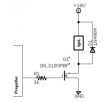
I am trying to design a simple circuit to provide 10A to an electric match in a rocket. I also want to be able to test the continuity of the circuit.
Is there a simple way to test the continuity with the prop? I was thinking a simple Mod on the attached circuit, running a low current through the ignitor by making the output pin on the prop an input and connecting it through a large resistor.
Please let me know what you all think, im not super strong on hardware design.
Thanks,
Alec
This probably has a very simple answer but its avoiding me.
I am trying to design a simple circuit to provide 10A to an electric match in a rocket. I also want to be able to test the continuity of the circuit.
Is there a simple way to test the continuity with the prop? I was thinking a simple Mod on the attached circuit, running a low current through the ignitor by making the output pin on the prop an input and connecting it through a large resistor.
Please let me know what you all think, im not super strong on hardware design.
Thanks,
Alec
366 x 344 - 11K
Comments
**Edit: fatally flawed design here**
Post Edited (originator) : 3/19/2007 5:37:07 AM GMT
Basically that idea is fine but if the Prop can detect a voltage then so can the mosfet, though it wouldn't quite work that way. Make the detection resistor a high value of around 100K or more and feed this into another input pin. The current is so low that the prop port can clamp it effectively from it's 10V but you can always add extra clamping.
I agree with using a resistor to the gate (for the purpose of protecting the port from catastrophic mosfet failure only) but make the value a little larger (10K) as you are not worried about nanosecond responses (RC delays). As was also pointed out you have nothing stopping the gate from floating high if the drive pin is not an output (during reset etc) so include a pulldown either on the port pin (this can be 100K or less) or from the gate. But watch out for the gate pulldown as you only have 3.3V drive and you would be forming a voltage divider.
Mike's suggestion is a good one as you would not want the rocket to be inadvertently fired. (I was just uploading new firmware and then it went KABOOM
How you do this can also be tricky but usually it's good to have a circuit that needs refreshing or else it defaults into the disabled state.
The diode across coil is unnecessary as the mosfet has an intrinsic clamp diode and is well able to handle the coil.
*Peter*
Thanks for the quick replies!
Orig, thanks for the diagram, its a great help!
Mike, I have a number of failsafes planned for pre-launch saftey (Breakwire etc.). Or are you meaning something more specific I need to design in to my circuit?
Thanks for that. I can sort of draw that in my head, will have to wait till im not at work try it out [noparse]:)[/noparse]
Any more suggestions/diagrams would be great.
I have a quick question, will taking the 10v for the firing circuit (its actually 9v) direct from the battery, prior to the regulator which provides the 3.3v, cause any trouble with the prop when this fires? I.e. Brownout etc.
Thanks,
Alec
1) I was just concerned since I didn't see any failsafes in your diagram.
2) You can run the 3.3V regulator off the 9V supply as long as your 9V supply can't drop below say 5V under the load of the ignitor.
Oh, that diagram was just a generic diagram of the net [noparse]:)[/noparse]
Its only a small part of the overall circuit.
It was a basic starting point to my requirments, the diagram which Orig posted seems to be alot better!
I have a basic understanding of electronic circuits but not with FET's, hence all my questions.
This forum would have to be one of the most helpfull I've seen!
Alec
Hi Orig,
I just found out the TIL191 is obsolete, would the attached product (SFH6943) be a good replacment? (Its a quad coupler which is fine as im planning on 4 pyro charges.)
Forgive me is this is a simple question, im new to opto's also
EDIT: Posted this just afer your reply Re. the 100k Resistor.
Thanks,
Alec
Post Edited (Basil) : 3/19/2007 3:04:20 AM GMT
Cool thanks. This should give me something to chew on.
Alec.
Hi Orig,
Forgive my ignorance, which opto are you refering to? OK1 or OK2
Also, with OK2 (The continuity Opto), is does not look like there is anything stopping the 12v passing through the ignitor and opto straight to ground.
Would this not be the same as shorting the ignitor and firing it? Or does the opto limit current somehow?
However, depending on how much current is required to fire the ignitor, at some value for the resisitor coming off the OK2 LED to GND, it will work, but that value is unknown without tests, and still would not be an ideal design.
The opto is a good practice for outputs of processors going to larger voltage devices, so the first opto is ok, it provides a layer of protection against the mosfet shorting and sending 10v straight to the Prop pin. I short mosfets all the time doing experiments with motors. When you are experimenting and learning about mosfets, always meter from the drain to gate, source to gate, drain to source prior to testing, especially if you are breadboarding, hobby boarding etc, it is just a good practice at first.
Ok, so in summary OK1 is fine for the ignition part, but you'd do something else for the continuity test rather than using the opto OK2?
Im still stuggling a bit with what to do for the cont. test part though as I cant seem to find a way to do it without firing the ignitor
The Prop reads if it is a 1, if so you have continuity, or you know the ignitor has "power". Can the ignitor fire off a 100k resistor to GND? I would say it is unlikely, just make sure the pin is always an input, not a low output just to play it safe.
Oh, takes me to miss that!
Thanks heaps, ill try those suggestions out and see how we go.
Ill try to think of a way to make that a bit safer too [noparse];)[/noparse]
Until tommorrow,
Alec
The MOSFET gate is essentially a capacitor with the other side effectively grounded. The gate series resistor and this capacitor make an RC circuit with the usual equation defining the charging time. A 100K resistor is just fine as long as you're not in a hurry, like trying to amplify a 20MHz signal without significant distortion or switch a bus signal in under 50ns. Typical gate capacitance is around 250pF.
I think that make sense.
Would if be something like the attached picture?
Oh, the electric matches typically·have test voltages of around 15ma -> 40ma and firing currents of 400ma -> 1A @ 9v
This has been a great learning experience!
Attached a circuit that I have personally used
for years with a BS2 STAMP (and other micro's) to drive
a very high speed solenoid valve.
The zener and diode across the SOLENOID (load) are there
for very rapid trun off.
The zener down the bottom is probably overkill but is it to
protect the GATE on the Mosfet from max high Volts (20VDC)
The resistor values will probably be close what you would want
in the 12-24VDC range...
The opto isolation on the left would get its signal from the PROP
Maybe insert a led in there for indication as well..
Remember you only 3.3VDC drive...
Cheers
Ronald Nollet Australia
Good morning
Thanks Ronald for that diagram.
Orig, that part got left behind on the rest of the circuit diagram, attached if how it should be
Thats a whole bunch of 100k resistors!
Thanks all, This looks like it should work.
Don't forget to put a physical switch in the ciruit somewhere just to be safe, maybe on the 9V input, enable the switch when everything is ready for continuity check + launch .
Hi Mike,
Okie tokie
Thanks for that.
Ill be standing well back when this is tested
I have a power switch, an 'Arm' switch and a failsafe, should be enough
Please make a video!!!!
Rich
Your circuit shows a voltage divider in the MOSFET gate circuit. With a high of 3.3V from the Propeller, the gate will see only 1.67V — not enough to turn it fully on. If the purpose of R1 is to limit inrush current to charge the gate capacitance, 100 ohms will suffice.
But even 3.3V won't be high enough for some "logic level" MOSFETs, since many were designed for 5V logic. Be sure to check the specs to make sure it will saturate with 3.3V on the gate.
-Phil