Shop OBEX P1 Docs P2 Docs Learn Events
Can this be done — Parallax Forums

Can this be done

computer guycomputer guy Posts: 1,113
edited 2008-06-01 22:49 in General Discussion
I am wanting to have message outputs on my project.

I am using the propeller chip.

I won't to use a maximum of 2 i/o pins.

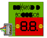
And look something like this. (with led display, like in picture)

attachment.php?attachmentid=45895

The messages will be like:

"A1"

"B3"

"11"

"20"

I will have a comparison table to reference e.g

| A1 | Battery Low |
| B3 | Out of range |

Thank you smile.gif

Post Edited (computer guy) : 3/14/2007 6:55:34 AM GMT
«1

Comments

  • T ChapT Chap Posts: 4,223
    edited 2007-03-14 07:05
    There could be an I2C 7 seg driver in existance, I don't know right off hand. There are several other simple options, here is one suggestion using an I2C PCF8575 i/o expander which is a 2 wire device that can have up to 8 connected on just 2 wires. Each IC has 16 i/o's, you could set up your data to output two bytes that represented a letter/number/symbol on the LED display. See this thread for the circuit and code sample. Other than I2c, you could probalby find a serial input 7 seg driver, but I don't see an instant benefit, with I2c you can run 8 7 seg displays though if needed.


    http://forums.parallax.com/showthread.php?p=636785

    The pic below shows the exact same concept, only using 2 x 10 segment bargraphs for feedback on a board that has lots of sensors to monitor. If you could use less than 8 LEDs in the display, there is a similar 8 i/o device called the PCF8574. With either device, the IC has address pins on it so you can select which one to update with the start byte shown in the code example.

    Post Edited (originator) : 3/14/2007 7:23:51 AM GMT
    337 x 795 - 80K
  • computer guycomputer guy Posts: 1,113
    edited 2007-03-14 07:21
    Is there some one who is happy to build this for me. coz i don't understand all this expanding i/o stuff.

    I just want it like a serial lcd.

    I send serial data via an i/o pin e.g "B3" and it comes up on the display as B3.

    Thank you smile.gif

    P.S if someone does do it for me i will be happy to negotiate a price.
  • T ChapT Chap Posts: 4,223
    edited 2007-03-14 07:28
    For something as simple as this, most people wont do it since it is such a small project. Why not just try it yourself and learn from the experience?
  • computer guycomputer guy Posts: 1,113
    edited 2007-03-14 07:36
    I have no idea what to do, i am a beginner at the propeller... well the most electronics work that i have done is build some kits.

    But my project needs this.

    If someone gave me a schematic of the final design and a parts list i could probably build it.

    By the way i have got a spare BS2 laying around if i could use that for some of the interface.

    Thank you smile.gif

    P.S although i don't know much about electronics i have spent my entire life working with kits ranging from led flasher kits using 555 timers
    up to led clocks.
    see www.jaycar.com.au/downloads/clock02.wmv
  • T ChapT Chap Posts: 4,223
    edited 2007-03-14 07:43
    If you want to waste the BS2 to driver some LEDs, then you could send a string from the Prop to the Stamp, write some code on the Stamp to output a series of pins to achieve the correct letter/numbes. You'd need only some resistors and some transistors. I don;t know how much total current the BS2 will sink, but I suppose there is a change it could run all the LEDs with only a resistor to each LED in the segment., you'd have to read the BS2 datasheet to see the total current for the IC. Plan on using some Darlinton transistor array like I linked above, the ULN2803 will be fine.

    Just get the Full Duples Object, study it a while and it is quite straighforward, you would need 1 wire from a designated Tx pin on the Prop to an Rx pin on the Stamp.

    Post Edited (originator) : 3/14/2007 7:55:27 AM GMT
  • computer guycomputer guy Posts: 1,113
    edited 2007-03-14 07:53
    Sorry i didn't see the schematic in your previous post i think i get it and that might be my best bet.

    Thank you smile.gif
  • computer guycomputer guy Posts: 1,113
    edited 2007-03-14 07:58
    Do ULN1-16 on the ULN2803's go to the ULN1-16 on the PCF8575 or directly to 3v3?

    Thank you smile.gif
  • T ChapT Chap Posts: 4,223
    edited 2007-03-14 08:06
    There are 10k's needed to pull up the outputs of the PCF8575. The output of the PCF8575 goes to both the "Input" of the ULN 2803 AND a 10k Resistor to +V (pullup)


    A resistor goes to the "output" of the ULN2803, that resistor goes to the LED, the other side of the LED goes to +V(5v is fine, adjust your current limiing resistor accordingly but 470 is a standard safe number.
  • computer guycomputer guy Posts: 1,113
    edited 2007-03-14 08:11
    So the ULN1-16 on the PCF8575 goes between the resistor on ULN1-16 and ULN1-16 on the ULN2803's.

    Like this:
    attachment.php?attachmentid=45898
    320 x 431 - 36K
  • T ChapT Chap Posts: 4,223
    edited 2007-03-14 08:16
    Sorry, I forgot those weren't showing the labels. Where you see the same Label, those get connected together.


    You can also look up the PCF8574 datasheet on GOogle, I think it will be the same but only 8 i'o. From what I can find, the PCF8575 is only available in an SMT package, but it is not super small, you could probably hand solder it.
    555 x 738 - 86K
  • computer guycomputer guy Posts: 1,113
    edited 2007-03-14 08:19
    Ok i think i have it.

    Thank you smile.gif
  • computer guycomputer guy Posts: 1,113
    edited 2007-03-14 08:21
    What program are you using for your schematics?

    Thank you smile.gif
  • T ChapT Chap Posts: 4,223
    edited 2007-03-14 08:24
    It appears that the 16 i/o version(PCF8575) is only available in SMT, but the 8 i/o 8574 comes in DIP or SMT.

    focus.ti.com/lit/ds/symlink/pcf8574.pdf

    Eagle
  • computer guycomputer guy Posts: 1,113
    edited 2007-03-14 08:26
    i can't find either of those components PCF8574/5 or ULN2803 in eagle 4.16r2 light.
  • T ChapT Chap Posts: 4,223
    edited 2007-03-14 08:36
    Put this in the Library and restart the app. You can easily modify the 8575 into the 8574(if you know what you are doing!)

    Post Edited (originator) : 3/14/2007 8:49:15 AM GMT
  • T ChapT Chap Posts: 4,223
    edited 2007-03-14 08:48
    I just updated the pcf lib to include the 8574 dip, you may need to press Library>update all after restarting the app yo get it to appear.


    Don't forget, each i2c device needs it's own unique address, you can use the existing Prop EEPROM pins, pull both lines up with 4.7k. The EEPROM address = 000 set the first PCF to 001, then the second to 010.

    Post Edited (originator) : 3/14/2007 9:48:12 AM GMT
  • Desy2820Desy2820 Posts: 138
    edited 2007-03-14 09:49
    I'd consider using Bean's 4 digit I2C LED display....

    http://www.sparkfun.com/commerce/product_info.php?products_id=751

    I think it will do what you want, it's basically a 7 segment LED with I2C built in.· It does require 5 volts though, not sure if your design has any other 5 volt parts.· (Advertised at $3.95, not sure about minumum order requirements or shipping costs...)

    For breadboard use, you'll also need header pins, like the ones used in the Homework Board for servo connections.

    I·hope this helps!


    Post Edited (Desy2820) : 3/14/2007 9:54:42 AM GMT
  • computer guycomputer guy Posts: 1,113
    edited 2007-03-14 09:58
    That looks great, will use that.

    Can someone convert the example code to work with the propeller.

    The demo programs can be found here:
    www.hc4led.com

    Thank you smile.gif
  • computer guycomputer guy Posts: 1,113
    edited 2007-03-15 07:29
    If anyone has started on the code (doubt it).
    Don't worry, Bean only ships to USA and i live in Australia.

    Looking at pictures of beans display it looks as if he is also using an i2c chip. How come he can use serial

    SHIFTOUT Dat, Clock, MSBFIRST,[noparse][[/noparse]segments(3), segments(2), segments(1), (segments(0) >> 1)\7]


    to communicate with it. however with the above circuit i have to use i2c functions?

    i2c.write


    Thank you smile.gif

    Post Edited (computer guy) : 3/15/2007 7:58:28 AM GMT
  • T ChapT Chap Posts: 4,223
    edited 2007-03-15 08:11
    "SPI LED 4 Number Display"

    Check into the difference between SPI and I2C
  • Bruce BatesBruce Bates Posts: 3,045
    edited 2007-03-15 08:19
    Computer Guy -

    SPI and Microwire chip implementations may look outwardly, at the hardware level, very much like I2C implementations. Herein lie the salient differences:

    SPI and Microwire - Synchronous serial access method implementation, external or hardware device addressing. PBASIC commands SHIFTIN/SHIFTOUT are used for access.

    I2C - Synchronous serial access method implementation, internal or software device addressing. PBASIC commands I2CIN/I2COUT are used for accessing the chip, or the chip is "bit banged" to simulate I2C commands.

    Regards,

    Bruce Bates

    ▔▔▔▔▔▔▔▔▔▔▔▔▔▔▔▔▔▔▔▔▔▔▔▔
  • computer guycomputer guy Posts: 1,113
    edited 2007-03-15 08:28
    Ok i am going to give you more info.

    I want a display:

    1. That is small (max 20cmx10cm LxH).
    2. Red/Blue/Green
    3. Preferably not LCD
    4. Can be controlled with a maximum of 4 i/o pins.
    5. That does NOT use bit's i.e ( i2c.write(25, %10000000) 'first byte ).

    Thank you smile.gif
  • computer guycomputer guy Posts: 1,113
    edited 2007-03-15 10:27
    This might help people come up with some ideas:

    www.kmitl.ac.th/~kswichit%20/Led/schematic.pdf

    Thank you smile.gif
  • computer guycomputer guy Posts: 1,113
    edited 2007-03-16 05:33
    Bean sent me a pm with this link and i think i will get one.

    www.rentron.com/SLED-C4.htm

    Thank you all smile.gif
  • computer guycomputer guy Posts: 1,113
    edited 2007-03-16 06:38
    Just a thought could i use the MAX7219 that parallax sells
    www.parallax.com/detail.asp?product_id=603-00001

    Thank you smile.gif

    Post Edited (computer guy) : 3/16/2007 8:53:38 AM GMT
  • computer guycomputer guy Posts: 1,113
    edited 2007-03-17 09:15
    echo...echo smile.gif
  • PJAllenPJAllen Banned Posts: 5,065
    edited 2007-03-17 11:27
    You could make a 7-segment controller using an SX28 which could take data serially (asynch., one wire and GND.)

    [noparse][[/noparse] Please don't Reply with "ok, how do I do that?" ]
  • computer guycomputer guy Posts: 1,113
    edited 2007-03-19 20:42
    In another post i finally decided to go down the i2c path.
    computer guy said...

    So this circuit with this code?

    With the 2x 7 seg display being Common Anode.

    Send output low to give led ground and turn led on.


    OBJ
      i2c   :   "minimali2cdriver"     ' THE OBJECT


    PUB start
           repeat
              makeDecision
    
    
    PUB makeDecision
        If someCondition == true
            Diplay77
        If anotherCondition == true
            Display55
    
    PUB Display77
        i2c.start(28)                                  'start the transaction, below the address pins are shown as %001
        i2c.write(28, %0100_001_0 + 0)    '   pin start(28), device type(0100), address(000), write mode(0)
        i2c.write(28, %11111111)              ' <<figure out what makes 7's, then set these bytes
        i2c.write(28, %11111111)              '<< figure out what makes 7's, then set these bytes
        i2c.stop(28)
    
    
    PUB Display55
        i2c.start(28)                                  'start the transaction
        i2c.write(28, %0100_001_0 + 0)    '   pin start(28), device type(0100), address(000), write mode(0)
        i2c.write(28, %11111111)              '<< figure out what makes 5's, then set these bytes
        i2c.write(28, %11111111)              ' <<figure out what makes 5's, then set these bytes
        i2c.stop(28)


    Post Edited (computer guy) : 3/21/2007 5:56:43 AM GMT
    534 x 393 - 43K
  • scott32scott32 Posts: 3
    edited 2007-03-21 05:48
    Bruce Bates said...
    Computer Guy -

    SPI and Microwire chip implementations may look outwardly, at the hardware level, very much like I2C implementations. Herein lie the salient differences:

    SPI and Microwire - Synchronous serial access method implementation, external or hardware device addressing. PBASIC commands SHIFTIN/SHIFTOUT are used for access.

    I2C - Synchronous serial access method implementation, internal or software device addressing. PBASIC commands I2CIN/I2COUT are used for accessing the chip, or the chip is "bit banged" to simulate I2C commands.

    Regards,

    Bruce Bates

    My question is what is the difference between using 2 wires I've seen for these protocols and other projects use 3 wires ( PIC )? Thank you
  • Bruce BatesBruce Bates Posts: 3,045
    edited 2007-03-21 06:37
    Scott -

    It really depends on what the three wires are doing. In some cases all that is happening is that the data input and data output are on separate pins. In other cases, the third wire may be for chip/device enable. In yet other cases, it may be an address line of sorts.

    I'm sure there are other protocals as well, but the key is knowing the purpose of the third wire.

    Regards,

    Bruce Bates

    ▔▔▔▔▔▔▔▔▔▔▔▔▔▔▔▔▔▔▔▔▔▔▔▔
Sign In or Register to comment.