Solder Pot Controller
Hello Everyone,
·
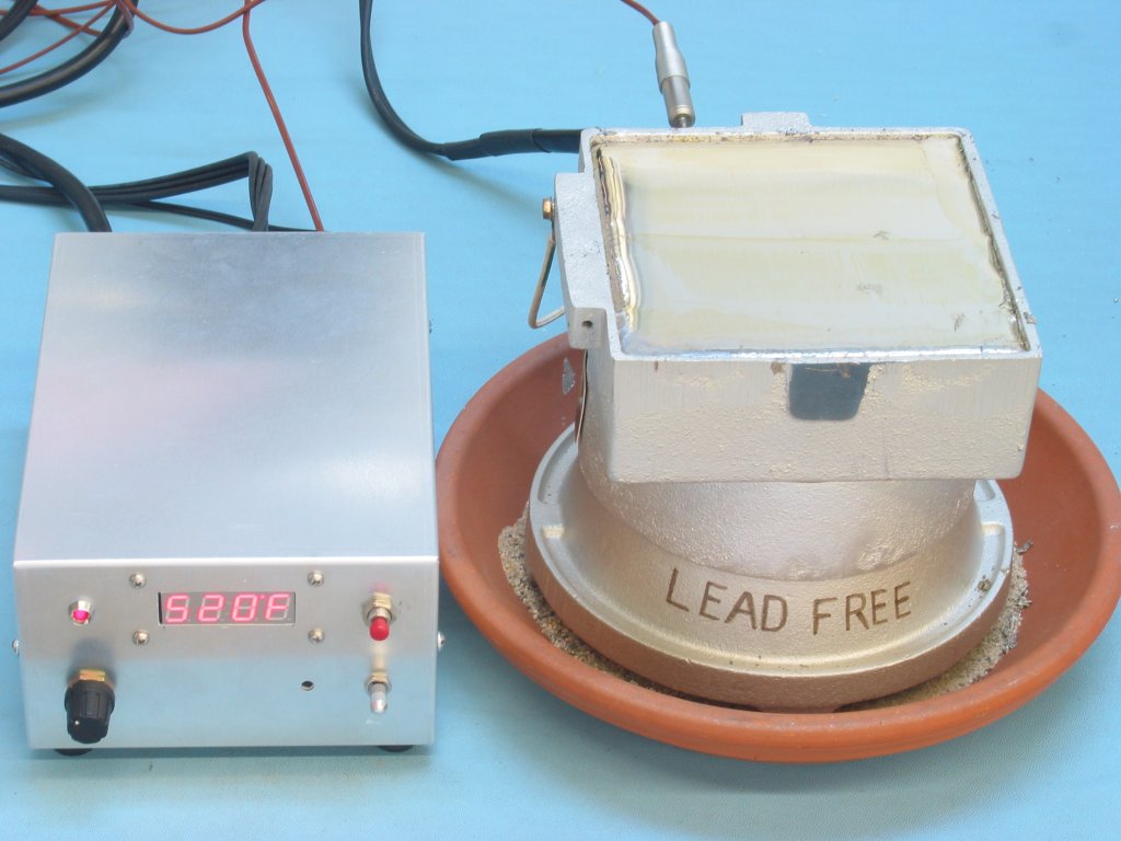
In 2006 to be RoHS compliant Parallax, Inc. moved toward making all products lead-free including the BASIC Stamp Modules which we manufacture in-house.· This required a new Lead-Free Solder Pot to·dip the modules in.· The new Solder Pot did not come with a temperature control.· Instead we created our own Solder Pot Controller which keeps the temperature at our specified set point.· The Solder Pot Controller does this by comparing the current temperature to the set temperature.· The current temperature is gotten via our own Thermocouple Kit and a pin probe which goes into the Solder Pot.
·
The Set Temperature is obtained by pressing a red safety button (which also displays the current set temperature) and rotating an encoder.· The allowed range is 450 – 550 degrees.· Once the desired set temperature is reached, releasing the button stores that value in EEPROM and the Solder Pot returns to comparing the temperature and turning the Solder Pot on/off as needed to maintain that temperature.
·
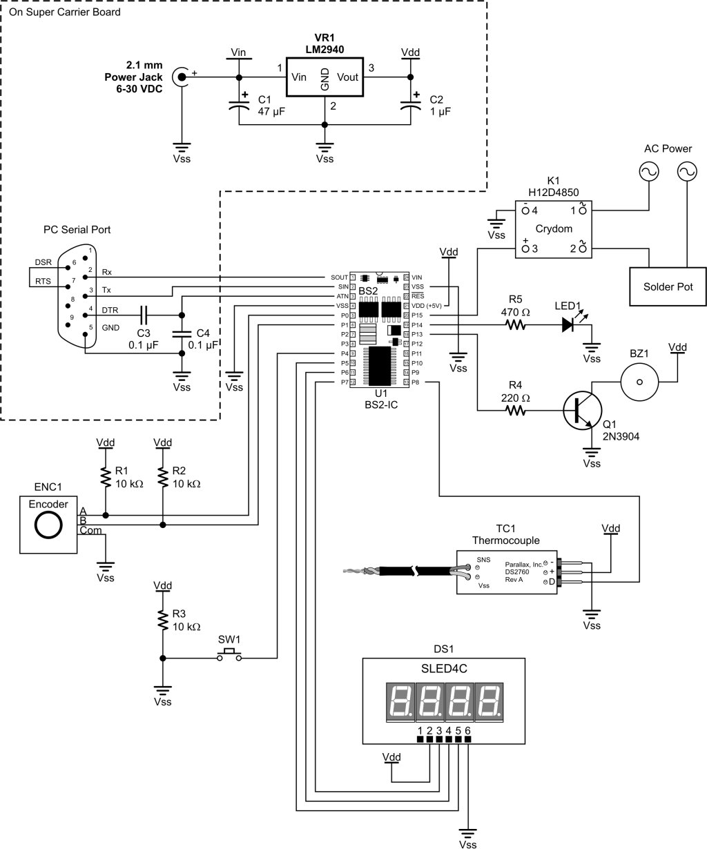
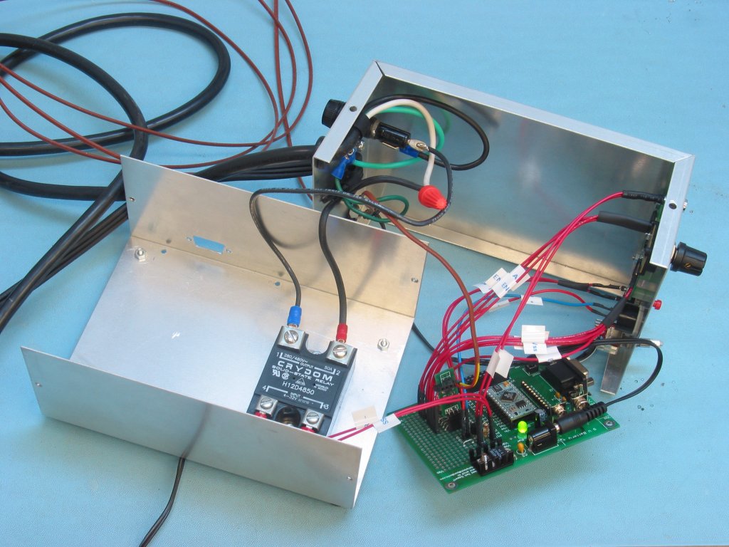
The optimum temperature for the lead-free parts is about 520 degrees.· The heating element in the Solder Pot is switched on via a Crydom H12D4850 Solid State Relay.· This relay is rated at 240/480V @ 50A and can switch the element on/off without any noise.· This allows for differential gap control without deteriorating controls as we had with the previous temperature controls.· Another problem was the connector right at the Solder Pot breaking down from apparent arcing.· This new system does not exhibit these symptoms.· Whenever the SSR is on an LED is also turned on to indicate the heating element is on.
·
One request our manufacturing department had was a way to know when the Solder Pot was up to temperature without having to keep going over and checking it (it takes a little while from a cold start to heat up).· A Piezo Buzzer is connected and when the Solder Pot first reaches its set temperature it beeps with three long beeps.· After this point the LED activity is much like a Soldering Station with the unit turning on/off at whatever rate is required to maintain the temperature and the buzzer is quiet.· Anything above or equal to the set temperature turns off the SSR.· Anything less turns it on.· The differential gap is 1 degree but could be expanded if necessary.· For this application it is not necessary due to the slow change in temperature in the pot due to density.
·
A schematic of the Solder Pot Controller is attached as well as the BASIC Stamp Code and some pictures.· The schematic and controls were well thought out.· The code was basically the Thermocouple Demo Code with what we didn’t need pulled out and what we did need put in.· The display is a Rentron Serial LED Display that we happened to have on hand.· There is also a FUSE on the incoming AC rated for just over the maximum current expected.· This can be seen in the pictures but was omitted from the schematic for clarity.· Due to the 1-Wire interface this will only work on a BS2p, BS2pe or BS2px model BASIC Stamp.
·
The code and schematics are provided as-is and Parallax, Inc. cannot be held responsible for any use of the information provided here.· For any questions please post them in this thread only.· Thank you!· Enjoy!
▔▔▔▔▔▔▔▔▔▔▔▔▔▔▔▔▔▔▔▔▔▔▔▔
Chris Savage
Parallax Tech Support
Post Edited (Chris Savage (Parallax)) : 3/10/2007 2:11:04 AM GMT
·
In 2006 to be RoHS compliant Parallax, Inc. moved toward making all products lead-free including the BASIC Stamp Modules which we manufacture in-house.· This required a new Lead-Free Solder Pot to·dip the modules in.· The new Solder Pot did not come with a temperature control.· Instead we created our own Solder Pot Controller which keeps the temperature at our specified set point.· The Solder Pot Controller does this by comparing the current temperature to the set temperature.· The current temperature is gotten via our own Thermocouple Kit and a pin probe which goes into the Solder Pot.
·
The Set Temperature is obtained by pressing a red safety button (which also displays the current set temperature) and rotating an encoder.· The allowed range is 450 – 550 degrees.· Once the desired set temperature is reached, releasing the button stores that value in EEPROM and the Solder Pot returns to comparing the temperature and turning the Solder Pot on/off as needed to maintain that temperature.
·
The optimum temperature for the lead-free parts is about 520 degrees.· The heating element in the Solder Pot is switched on via a Crydom H12D4850 Solid State Relay.· This relay is rated at 240/480V @ 50A and can switch the element on/off without any noise.· This allows for differential gap control without deteriorating controls as we had with the previous temperature controls.· Another problem was the connector right at the Solder Pot breaking down from apparent arcing.· This new system does not exhibit these symptoms.· Whenever the SSR is on an LED is also turned on to indicate the heating element is on.
·
One request our manufacturing department had was a way to know when the Solder Pot was up to temperature without having to keep going over and checking it (it takes a little while from a cold start to heat up).· A Piezo Buzzer is connected and when the Solder Pot first reaches its set temperature it beeps with three long beeps.· After this point the LED activity is much like a Soldering Station with the unit turning on/off at whatever rate is required to maintain the temperature and the buzzer is quiet.· Anything above or equal to the set temperature turns off the SSR.· Anything less turns it on.· The differential gap is 1 degree but could be expanded if necessary.· For this application it is not necessary due to the slow change in temperature in the pot due to density.
·
A schematic of the Solder Pot Controller is attached as well as the BASIC Stamp Code and some pictures.· The schematic and controls were well thought out.· The code was basically the Thermocouple Demo Code with what we didn’t need pulled out and what we did need put in.· The display is a Rentron Serial LED Display that we happened to have on hand.· There is also a FUSE on the incoming AC rated for just over the maximum current expected.· This can be seen in the pictures but was omitted from the schematic for clarity.· Due to the 1-Wire interface this will only work on a BS2p, BS2pe or BS2px model BASIC Stamp.
·
The code and schematics are provided as-is and Parallax, Inc. cannot be held responsible for any use of the information provided here.· For any questions please post them in this thread only.· Thank you!· Enjoy!
▔▔▔▔▔▔▔▔▔▔▔▔▔▔▔▔▔▔▔▔▔▔▔▔
Chris Savage
Parallax Tech Support
Post Edited (Chris Savage (Parallax)) : 3/10/2007 2:11:04 AM GMT


Comments
▔▔▔▔▔▔▔▔▔▔▔▔▔▔▔▔▔▔▔▔▔▔▔▔
Chris Savage
Parallax Tech Support
Post Edited (Chris Savage (Parallax)) : 3/10/2007 6:31:15 PM GMT
▔▔▔▔▔▔▔▔▔▔▔▔▔▔▔▔▔▔▔▔▔▔▔▔
Chris Savage
Parallax Tech Support
Thanks once again Chris....Twisted Pair....
▔▔▔▔▔▔▔▔▔▔▔▔▔▔▔▔▔▔▔▔▔▔▔▔
Chris Savage
Parallax Tech Support
▔▔▔▔▔▔▔▔▔▔▔▔▔▔▔▔▔▔▔▔▔▔▔▔
Chris Savage
Parallax Tech Support
▔▔▔▔▔▔▔▔▔▔▔▔▔▔▔▔▔▔▔▔▔▔▔▔
Chris Savage
Parallax Tech Support
Thanks, Twisted Pair....
Thanks....
http://lgrws01.grayhill.com/web/images/ProductImages/I-51-52.pdf
▔▔▔▔▔▔▔▔▔▔▔▔▔▔▔▔▔▔▔▔▔▔▔▔
Chris Savage
Parallax Tech Support
Thanks Chris....
▔▔▔▔▔▔▔▔▔▔▔▔▔▔▔▔▔▔▔▔▔▔▔▔
Chris Savage
Parallax Tech Support
Twisted Pair....
--mark
The Solder Pot is only used for the through hole stuff…BASIC Stamp Modules for example…The leads are dipped on each side. The SMD stuff runs through another machine (conveyer/oven). Take care.
▔▔▔▔▔▔▔▔▔▔▔▔▔▔▔▔▔▔▔▔▔▔▔▔
Chris Savage
Parallax Tech Support
I'm putting together a project using the SX48 proto board and I wasn't completely clear on how to connect things. For the time being, I wire wrapped things together. I'm thinking that I'll just put some solder on the wire wrap connections when I'm ready to finalize the project.
▔▔▔▔▔▔▔▔▔▔▔▔▔▔▔▔▔▔▔▔▔▔▔▔
OS-X: because making Unix user-friendly was easier than debugging Windows
links:
My band's website
Our album on the iTunes Music Store
I never took a picture of the bottom…The schematic shows the connections though. I am only using P0, not P1…P0 is going directly to the PING))) Data Line. Take care.
▔▔▔▔▔▔▔▔▔▔▔▔▔▔▔▔▔▔▔▔▔▔▔▔
Chris Savage
Parallax Tech Support
I think you're thinking of the Garage Parking Assistant--I was looking at the Solder Pot Controller. But that doesn't really matter. What I really want to find out is how you connect things on a proto board (don't forget--I'm just a software guy
Thanks,
-Steve
▔▔▔▔▔▔▔▔▔▔▔▔▔▔▔▔▔▔▔▔▔▔▔▔
OS-X: because making Unix user-friendly was easier than debugging Windows
links:
My band's website
Our album on the iTunes Music Store
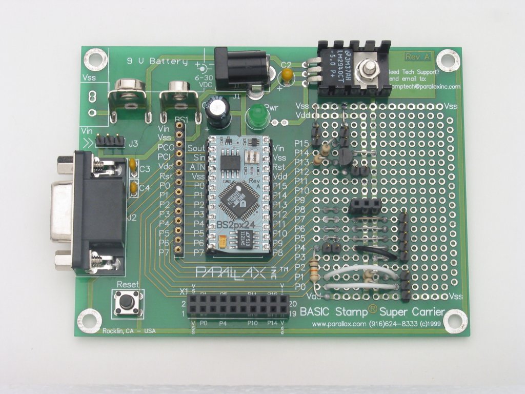
You are correct…I was in the wrong thread…Wire-wrapping…Ah I would be showing off my age…I haven’t done that since 1997! Anyway, to answer your question directly the Super Carrier Board already has traces connecting certain points on the board as well as two power busses. It’s kind of hard to see but if you looked closely at the board (large view) or at the schematic you could see where traces connect. I try to place components such that they complete circuits by default. But in the case of the Solder Pot controller I had a lot of connections so if you look at the board you will see standard 22 gauge wire jumpers I created to connect circuits. That is all I use. I have seen some people use wire-wrapping wire underneath. The problem is that you have to be very careful with that. The insulation is very thin and delicate and the heat from a soldering iron melts is quickly. I have seen many a board like that fail prematurely due to shorts in the wiring.
▔▔▔▔▔▔▔▔▔▔▔▔▔▔▔▔▔▔▔▔▔▔▔▔
Chris Savage
Parallax Tech Support
▔▔▔▔▔▔▔▔▔▔▔▔▔▔▔▔▔▔▔▔▔▔▔▔
OS-X: because making Unix user-friendly was easier than debugging Windows
links:
My band's website
Our album on the iTunes Music Store
Got to the following web page and click on the larger picture view. Also check out the Schematic lower on the page. I have always found the Super Carrier Board to be great for small one-off projects because it includes most of the necesseties and makes it easy to add several external components. If you look closely at the third picture of the Solder Pot Controller opened up you can see where we cut out an exact hole for the DB9 to protrude through the cabinet. This allows for easy code updates without having to take the unit apart. Take care.
http://www.parallax.com/detail.asp?product_id=27130
▔▔▔▔▔▔▔▔▔▔▔▔▔▔▔▔▔▔▔▔▔▔▔▔
Chris Savage
Parallax Tech Support
Thanks,
Twisted Pair....
Did you change the Set Point range from 450-550 to the range you’re going to be in? Did the displayed temperature increase as you applied heat?
▔▔▔▔▔▔▔▔▔▔▔▔▔▔▔▔▔▔▔▔▔▔▔▔
Chris Savage
Parallax Tech Support
Didn't change anything other than when running the program to the BS2P. As far as displaying the Temp, I haven't connected the one wire SLED-C4 because I'm unsure of what or where to change from Shiftin to Serout, so I cant see anything, Just watching the Led....
Twisted Pair....
setTemp VAR Word
SetTemp = 100
WRITE 0, Word setTemp
▔▔▔▔▔▔▔▔▔▔▔▔▔▔▔▔▔▔▔▔▔▔▔▔
Chris Savage
Parallax Tech Support
Thanks once again Chris,
Twisted Pair....
▔▔▔▔▔▔▔▔▔▔▔▔▔▔▔▔▔▔▔▔▔▔▔▔
Chris Savage
Parallax Tech Support