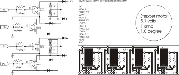
stepper motor circuit
Just got my first Basic Stamp homework board, and put this circuit together from page 264 and other circuits online,· my question is, Will it work?·· I am new at this and would welcome the help.
Can the power supply be 7.5 volts 1 amp, or do this circuit requires more power?
Is this Circuit OK?
Can the power supply be 7.5 volts 1 amp, or do this circuit requires more power?
Is this Circuit OK?


Comments
First understand the fundamentals of what needs to happen to spin a unipolar stepper. There are 4 coils. The coils need to be turned on in sequence by the Stamp. The center of each coil goes to +V, that means you have to SWITCH the GND on and off to make it run. This switching is done with the transistor, a diode is used across the coil to prevent the voiltage being "generated" from flowing back to the transistor. There are 9 million stepper circuits on google, maybe you have seen them. Picture in your mind the 4 coils that permanently have the +V to them, and you need to shunt to GND the side left open on each coil. The transistor acts like a relay when a signal is put to it's gate. The gate is just that, a way to allow the current to flow.
Here is a much simpler way to go, with much less parts. There are newer versions of the transistor array, try a ULN2803 which contains 8 darlington transistors and built in diodes. This is just a sample schematic, the lines on pin 2 and 3 do not need to be reveresed on the Stamp.
http://www.doc.ic.ac.uk/~ih/doc/stepper/control2/gif/connect4.gif
Hereis another variation:
http://hades.mech.northwestern.edu/wiki/index.php/Image:Unipolar_stepper_circuit_schematic.png
Post Edited (originator) : 3/10/2007 6:03:19 AM GMT
Will the ULN2003 be able to handle 5.1 volts at 1 amp?·· I check the URL address you gave me and it saids, that the ULN2003 and 2803 can handle up to 500ma.· that's why I was making this circuit with Radio Shack Mosfet that can handle up to 3 amps.
Post Edited (willy1067) : 3/10/2007 6:01:12 AM GMT
Here is a suggestion only, the more fundamentals you can get the better. Take the stepper motor, run 5 volts to the center of the coil. Then take one of the other wires (probably 4 wires) and touch one of them to GND. See if you can figure out the sequence to manual get the motor to move in a direction, then, find out how to reverse it. I forget, but with unipolat you may be able to keep it going with only one wire, some parts of the "sequence" may require 2 wires at a time though, find a unipolar single step sequence chart and note what combinations are ON to move it one step. This will help you "see" what is going on.
Personally, I would hook up the motor with one of the schematics I linked, and try it out. Then again, I have blown up a whole lot of stuff. Keep checking the transistors when you first power up a new circuit, they will get very hot early on if there is a problem. Keep one hand on the power just in case.
Post Edited (originator) : 3/10/2007 6:16:57 AM GMT
http://forums.parallax.com/showthread.php?p=637017
▔▔▔▔▔▔▔▔▔▔▔▔▔▔▔▔▔▔▔▔▔▔▔▔
Chris Savage
Parallax Tech Support