

$10 stepper motor controller and robotic hand
 willy1067
Posts: 107
willy1067
Posts: 107
Moved The $10 stepper motor controller project to the (COMPLETED PROJECT)· here is the shortcut;
·http://forums.parallax.com/showthread.php?p=641371
I will keep this for the robotic arm and my progress
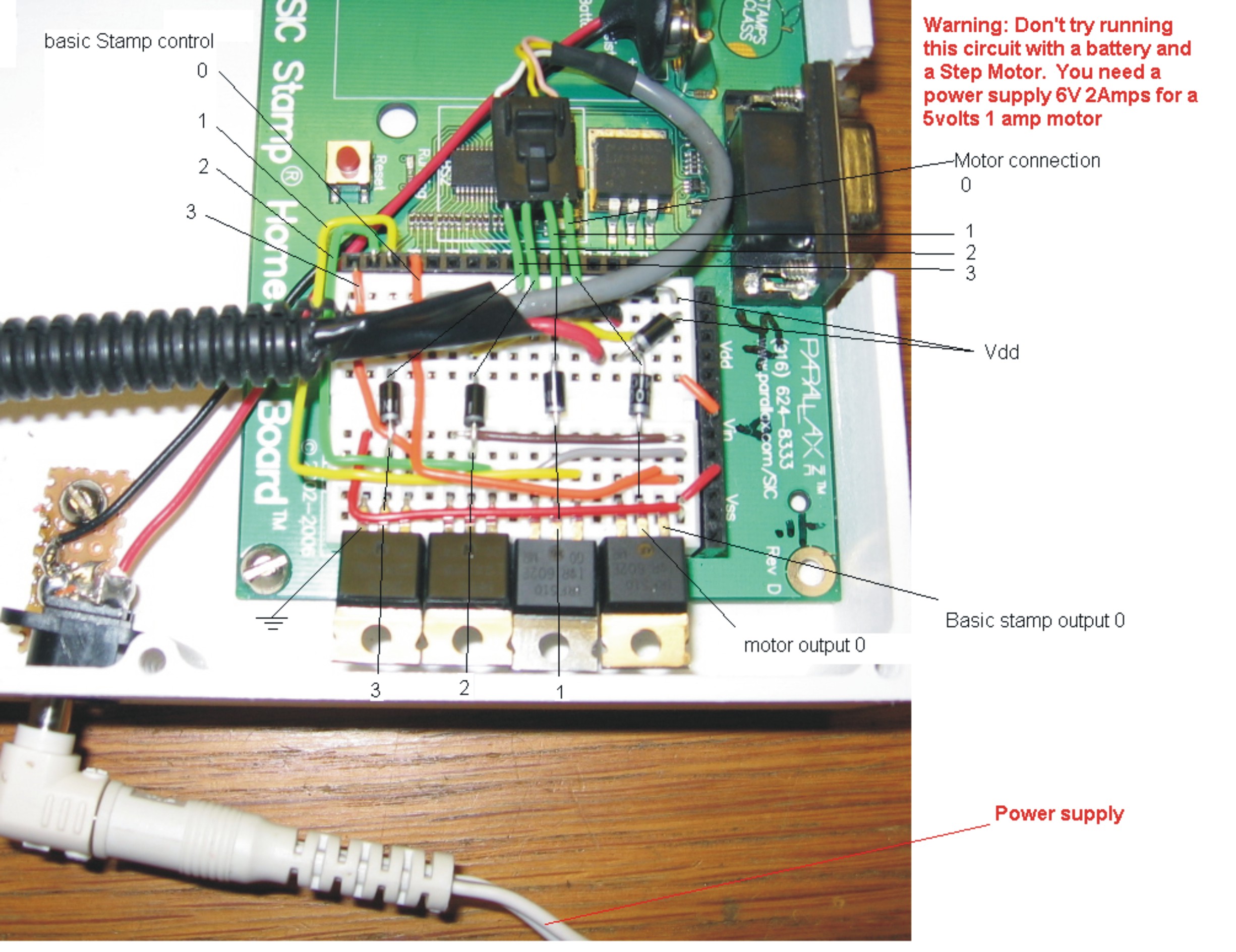
Just got my first Basic Stamp homework board, and put this circuit together from page 264 and other circuits online,· my question is, Will it work?·· I am new at this and would welcome the help.
Can the power supply be 7.5 volts 1 amp, or do this circuit requires more power?
Is this Circuit OK?
·http://forums.parallax.com/showthread.php?p=641371
http://www.youtube.com/watch?v=LGQ7sTf4diM·· (CNC Routing part)
http://www.youtube.com/watch?v=Xj86rqmcctM·· (Finished part)
http://www.youtube.com/watch?v=BLULfaNhOFg· (first movement)·
NOTE: This circuit works, I will post a board soon. also I use Radio Shack 6 Volts, 2 Amps to power both the motor and the Basic Stamp Homework Board.
http://pinellas-sign-manufacturer.com
▔▔▔▔▔▔▔▔▔▔▔▔▔▔▔▔▔▔▔▔▔▔▔▔
Fernando Gomez
Never compare yourself with anyone else, there will always be someone bigger·or·smaller·than you.
Post Edited (willy1067) : 12/14/2008 6:30:10 PM GMT
·http://forums.parallax.com/showthread.php?p=641371
I will keep this for the robotic arm and my progress
Just got my first Basic Stamp homework board, and put this circuit together from page 264 and other circuits online,· my question is, Will it work?·· I am new at this and would welcome the help.
Can the power supply be 7.5 volts 1 amp, or do this circuit requires more power?
Is this Circuit OK?
·http://forums.parallax.com/showthread.php?p=641371
http://www.youtube.com/watch?v=LGQ7sTf4diM·· (CNC Routing part)
http://www.youtube.com/watch?v=Xj86rqmcctM·· (Finished part)
http://www.youtube.com/watch?v=BLULfaNhOFg· (first movement)·
NOTE: This circuit works, I will post a board soon. also I use Radio Shack 6 Volts, 2 Amps to power both the motor and the Basic Stamp Homework Board.
http://pinellas-sign-manufacturer.com
▔▔▔▔▔▔▔▔▔▔▔▔▔▔▔▔▔▔▔▔▔▔▔▔
Fernando Gomez
Never compare yourself with anyone else, there will always be someone bigger·or·smaller·than you.
Post Edited (willy1067) : 12/14/2008 6:30:10 PM GMT
2048 x 1536 - 623K
599 x 399 - 19K
2451 x 1888 - 600K
261 x 348 - 18K
626 x 469 - 56K
Comments
As long as you understand that the Stepper Needs to be powered separately from the H/W Board and that the board and Stepper Supply need a common ground you should be okay. Most Stepper Motors can handle a little more voltage than what they’re rated at. Take care.
▔▔▔▔▔▔▔▔▔▔▔▔▔▔▔▔▔▔▔▔▔▔▔▔
Chris Savage
Parallax Tech Support
Post Edited (willy1067) : 3/10/2007 5:31:54 AM GMT
There are examples even on these forums where people have posted their circuits and gotten help. You won’t be able to power the Stepper Motor from the H/W Board. I’m guessing you knew that since you got a beefier supply. On the circuit you posted you would connect that to the V+ terminal. It may be possible to also feed that power to the H/W Board’s battery terminals without issue. Perhaps you should go ahead and try that. But do not connect any power from the H/W Board Vdd line to your circuit as the on-board regulator won’t be able to supply enough current. Take care.
▔▔▔▔▔▔▔▔▔▔▔▔▔▔▔▔▔▔▔▔▔▔▔▔
Chris Savage
Parallax Tech Support
Remember, the equivalent resistance of two resistors wired·in parallel is (R1 x R2) / (R1 + R2), or in the case of your two 100-ohm resistors, it would be 10000 / 200 = 50 ohms. So, you could replace the two 100 ohm resistors with one 50-ohm resistor. I think Parallax used two 100-ohm resistors in parallel in the WAM manual because the WAM kit didn't have any 50-ohm resistors but did have 100-ohm resistors, and they wanted to bias that particular transistor with 50 ohms equivalent.
PAR
Also on Page 99 of the Basic Stamp 1 manual there is an App note on using steppers. "a serial stepper controller" It uses a simple circuit and a ULN 2003 (the ULN 2003 looks like it's just a pack of eight transistors)
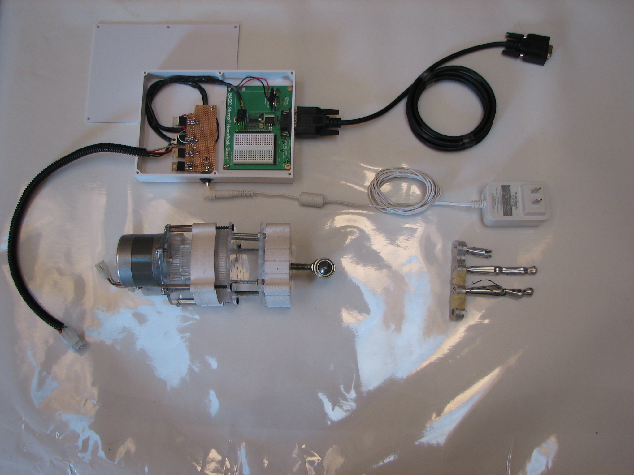
for some reason or another, three of them worked, one didn't. I thought it was a bad transistor and replaced it, but again it didn't work. So I desided to step back and install the conponents on the Basic Stamp Homework board. Yahooo.. it works. I added picture of the project in progress. Thanks guys...
Post Edited (willy1067) : 3/24/2007 8:20:57 PM GMT
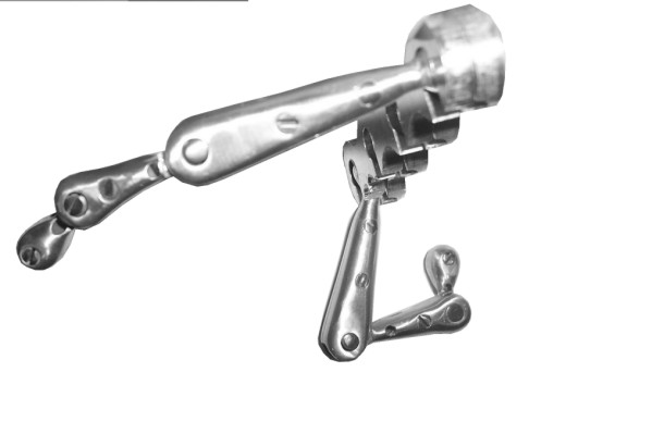
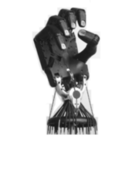
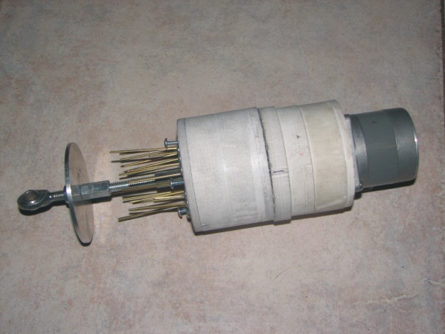
Is that a spherical bushing I see attached to the shaft of the stepper in the picture titled "Upper arm section.jpg?"
--Bill
▔▔▔▔▔▔▔▔▔▔▔▔▔▔▔▔▔▔▔▔▔▔▔▔
You are what you write.
Would you mind describing how you connected the lateral side of the spherical bushing to the stepper motor? I am in the process (collecting parts and thinking) of building an articulated spine using spherical bushings. I buy spherical bushings from vbx.com. Do you have a better source?
The pictures you posted look great.
Thanks and good luck!
--Bill
▔▔▔▔▔▔▔▔▔▔▔▔▔▔▔▔▔▔▔▔▔▔▔▔
You are what you write.
In a human wrisk, we can move our hands 180* degree up and down, and from side to side only about 45*. so for my design a spherical bushing will work fine, by attaching the stepper motor to a screw lead, the washer will move down and up, moving to the desire position.
I attached a drawing.
Now if you are building a articulating spine, I made something different.
Ball bearings attached to circular blocks, milled down on top and botton the route both to the circuference of the ball bearings. by changing the position of each (springs, actuators, or anything you can think of) will change the shape of the spine.
I attached another drawing next to it. hope that can help you
(I removed the picture of the upper arm assembly to post you the illustration, let me know when you load it to your computer to put it back.)
NOTE TO ALL: I removed the old picture for the circuit, and updated it with a new one.
▔▔▔▔▔▔▔▔▔▔▔▔▔▔▔▔▔▔▔▔▔▔▔▔
Fernando Gomez
revinc.us
gomez-rivera.com
Never compare yourself with anyone else, there will always be someone bigger·or·smaller·than you.
Post Edited (willy1067) : 3/28/2007 9:52:54 PM GMT
Thank you very much for posting the drawings! Your articulated spine ideas are (somewhat) similar to mine. Soon, I will start experimenting with ideas as I am going to buy a mill to make parts.
--Bill
▔▔▔▔▔▔▔▔▔▔▔▔▔▔▔▔▔▔▔▔▔▔▔▔
You are what you write.
sorry guys about the loop, Do command (they where in reverse)
▔▔▔▔▔▔▔▔▔▔▔▔▔▔▔▔▔▔▔▔▔▔▔▔
Fernando Gomez
revinc.us
gomez-rivera.com
Never compare yourself with anyone else, there will always be someone bigger·or·smaller·than you.
·http://forums.parallax.com/showthread.php?p=656332·(CNC Project)
·http://www.youtube.com/watch?v=LGQ7sTf4diM (CNC Routing part)
·http://www.youtube.com/watch?v=Xj86rqmcctM (Finished part)
·http://www.youtube.com/watch?v=BLULfaNhOFg (first movement)·· (video·being processed)
·http://pinellas-sign-manufacturer.com
▔▔▔▔▔▔▔▔▔▔▔▔▔▔▔▔▔▔▔▔▔▔▔▔
Fernando Gomez
Never compare yourself with anyone else, there will always be someone bigger·or·smaller·than you.
Post Edited (willy1067) : 12/12/2008 10:35:34 PM GMT