

Ft232RQ
 T Chap
Posts: 4,260
T Chap
Posts: 4,260
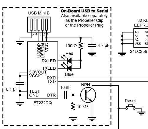
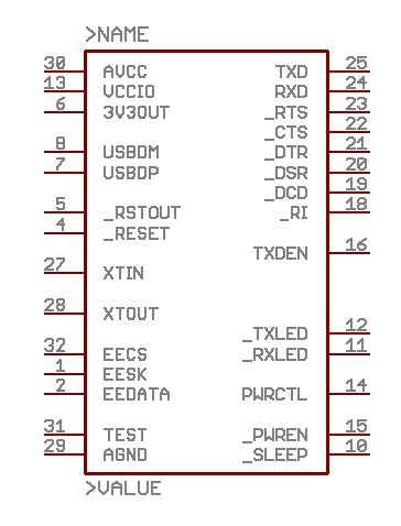
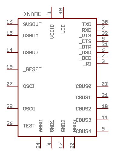
The FTDI site links to the Eagle site(cadsoftusa.com) for the FTDI Eagle libraries. When looking at the Prop demo board shown below, it shows a different part for the FT232RQ than what actually appears in Eagle. Clearly the Eagle Library is wrong but I wanted to make sure. The Eagle library for the FR232RQ doesn't even have the RX or TX leds. It also lists a lot of Cbus pins. I uploaded the Eagle parts as they are labeled, I think that someone has the parts reversed in Eagle.
503 x 437 - 43K
364 x 478 - 26K
383 x 514 - 27K
Comments
*Peter*
yous should read FTDI's datasheet.
http://www.ftdichip.com/Documents/DataSheets/DS_FT232R.pdf
The CBUS pins are configurable and can be used as general I/O's, or
for special functions like RX/TX-LED.
I'd say the eagle part is ok.
- Karl
I was working on a circuit to allow both USB and RS232 programming. I justified the need based on the fact that maybe there could be a case where the FTDI drivers weren't installed, or some other driver conflict existed, and someone needed to update a program.
If I continue with the ORing of the RESn, what would be the best method to take the RESn low via either FT232R DTR or the RS232 DTR lines? I was purely guessing to use just one transistor, sum the two DTR's with a 1k into the single AC coupling cap which should still produce a transient.
For the Prop Rx, I think a simple use of an OR gate would be fine from either source.
**Thanks for the clarification on the library part.
Post Edited (originator) : 3/7/2007 9:36:21 AM GMT
??? ..... that's what I said.
*Peter*
When the DTR goes from low to high the capacitor is being charged and current flows through the base of the npn to ground turning the npn on and pulling the collector low, which is the reset line. As the cap charges the current tapers off until the npn turns off and releases the reset signal. You won't be able to generate a reset again until the capacitor is discharged by pulling DTR low and then it discharges through the resistor. So the RC combo has a time constant that has to be met before the cap is sufficiently discharge but that's not important here, the main thing is that the DTR doesn't hold the CPU in permanent reset.
BTW, the DTR line is normally high when the port is disconnected and is low when it is connected. So a reset pulse is generated when the port is disconnected.
If you sum the two outputs you would end up with 0V, 1.65V, or 3.3V and basically you will find that it would sit at 3.3V and only ever go to 1.65V which may be effectively insufficient to trigger the npn. But you could make it work as it only needs a short reset pulse anyway. Alternatively connect diode cathodes to the DTR and a 3K3 pullup on the common anode side should allow you to drive the cap fully.
You need to do something about or'ing the TXD lines together to the Propeller which you can do simply with diodes connected cathode to TXD and common anodes to RXD with a suitable pullup resistor of around 3K3 or less.
Hell, by the time you muck about with diode or'ing you may as well get a 74HC00 quad nand gate for 20 cents and use that instead as a dual 2-input AND gate which effectively works as a negated input NOR (don't worry, it works). I just read your last line, no, an OR gate won't work as the signal is active low.
*Peter*
From the schematics I have seen, it appears that the output of the transistor/RESn is floating until pulsed, is the RESn pin internally pulled up?
Post Edited (originator) : 3/7/2007 7:37:18 PM GMT