

$40 6-Channel RC System
 JonnyMac
Posts: 9,809
JonnyMac
Posts: 9,809
Here's how: Buy a VEX Transmitter and Receiver kit for $30 (that's $100 less than what the VEX folks charge for it) from All Electronics (www.allelectronics.com) and add a $10 SX28 Proto Board to convert the PPM output from the receiver to usable servo pulses. I wrote two versions of the program; one that controls six servos, the second that converts channels 5 and 6 (controlled with buttons on the bottom side of the transmitter) to toggled digital outputs.
I used 5 volts to power the reciever.
Post Edited (JonnyMac) : 3/3/2007 6:18:11 AM GMT
I used 5 volts to power the reciever.
Post Edited (JonnyMac) : 3/3/2007 6:18:11 AM GMT

Comments
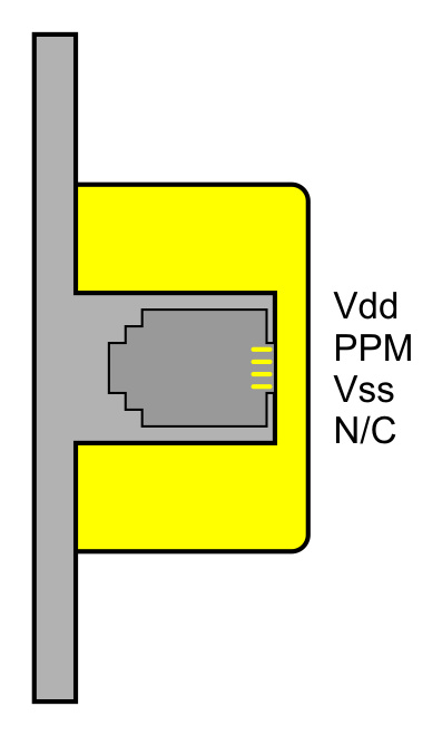
4 : N/C
3 : Vss
2 : PPM -- pulled up via 10K; connected to RA.0
1 : Vdd
I have no interest in PICs or AVRs so I can't help you much there, except to say that the source code is in Basic and doesn't use any clever tricks; anyone with a small degree of programming skill should be able to translate it to any processor of their choice.
And the most one would have to spend on Parallax goodies is about $40: $30 for an SX-Blitz programmer and $10 for and SX28 proto board. Still, if you add these to the cost of the VEX TX/RX kit from All Electronics, it's cheaper than what the VEX folks charge -- and you have a tool for programming the SX chip which is fast and well-supported. And the language compiler I used, SX/B, is FREE.
- Sparks
I bought one of these RCs but was sadly disappointed when I found that these were using "proprietary" protocol, and just decided that one of these days I should try to decode the signals with a scope, but never got around to do that.
Jon, what is the slowest I can run the SX using this program? I want the chip to consume as little power as possible, leaving that precious battery for the servos themselves.
Man this forum is great, with truly great minds [noparse]:)[/noparse]
Dan
So, if I get it right, at 1us, that would basically be a NOP with the SX running at 1mhz? That would definitively not leave enough cycles for the pauseus command of SX/B .
I guess I could use a 5mhz resonator, that should be enough, then.
Try it at 4 MHz and see what happens. The compiler will complain if your FREQ setting is not compatible with the commands you're using. With 50 MHz, the clock timing is very fast so everything has better resolution -- but that doesn't matter here (I only had 50 MHz resonators in my toolbox when I wrote that program). Timing on this little project is not that critical since you're following an envelope after the break is detected.
The import thing to do -- that so many seem unwilling -- is simply play! Thank Goodness that Thomas Edison decided to play as much as he did; had he wanted the built-in answers so many in this forum come looking for (not you), we would never have had all his wonderful inventions.
Does anyone happen to know what the transmitting range, in feet, is on this RX/TX?
Thanks
▔▔▔▔▔▔▔▔▔▔▔▔▔▔▔▔▔▔▔▔▔▔▔▔
Mike
I hate to reinvent the wheel. By chance, has anyone converted the SX/B code to Stamp PBasic? If not, this will make a good holiday project.
Regards,
TCIII
▔▔▔▔▔▔▔▔▔▔▔▔▔▔▔▔▔▔▔▔▔▔▔▔
If you are going to send someone to save the world, you·better make sure that they like it the way it is!
- Sparks
http://forums.parallax.com/showthread.php?p=677332
▔▔▔▔▔▔▔▔▔▔▔▔▔▔▔▔▔▔▔▔▔▔▔▔
slashsplat
/* Ira Chandler */
http://BotConnect.com
Here is the program: hellspark.com/dm/ebench/sx/dave/VEX_Analog_to_Digital.SXB
I will also attach it to the post for the paranoid types [noparse]:D[/noparse]
ESC: http://www.hobby-lobby.com/boatcont.htm
(the bottom one is mechanically controlled and would work fine with a servo but i want to use the electronic controller) the generic hookup for the ESC's is 3-wire straight into the throttle axis connector on a mainstream RC reciever.
Thanks, Jarrett
what is the J2 header for?
Posted back on 3/5/2007 7:24 PM (GMT -8), JonnyMac said:
"Yes, J2 is the resonator socket -- I happened to use 50 MHz (you'll see that in the code listings; FREQ directive)."
Is that the "J2" you are asking about?
par
-noob [noparse];)[/noparse]
I think I can help clarify this. The "Rx" in the schematic is a resistor (usually 10K ohm) and not the resonator itself. It is very common to see a 10K resistor across the two OSC pins when using a resonator with the SX chips. On some you may also see a small (5pf cap) from one of the OSC leads to ground.
You still need to install the resonator itself.
Hope this helps.
Robert