

The Retrosys is born
 Sachiel7
Posts: 41
Sachiel7
Posts: 41
Hey everyone,
I'd just like to post some info on my latest project utilizing the power of the Propeller chip, the Retrosys.
Its a game console, much like the Hydra (to whom I gladly tip my hat), here are some of it's features:
-Two SEGA Genesis controller ports·w/ six button support, ability to interface to other
·peripherals
-TV Out (No VGA, I wanted to treat it as more of a standard console)
-Stereo sound output ( )
)
-2MB Dedicated Video EEPROM (Two banks of 1 MB each, For tilemaps, possible 3D data)
-1MB Dedicated Audio EEPROM (For sequences and samples)
-1MB Dedicated Extra EEPROM (Could be used for game stats, physics object storage, etc)
-128 MB internal DataFlash for application and data storage
-PC-Connectivity through USB (obviously), planned NetPlay over PCs with active internet connection
These are some of the main points of my system. Each memory Bank can be accessed simultaniously by the propeller to fully utilize the multiprocessing and object-based coding.
Now, I do not claim to be the best at designing PCB layouts! (or systems, for that matter)·I am not an EE, I'm actually an ME with several years of controls system experience, but I have been a programmer for years now. I referenced the Propeller Demo board while laying out my board.
I've posted a snapshot of my PCB layout for the system below. I've worked on it in my freetime for about a month or two now, and thought some feedback would be nice. I also included the .pcb file, which can be viewed with ExpressPCB from expresspcb.com, if you havent heard of it before.
I ordered two of these boards, as well as my first chunk of components (Prop chip and clip, mostly). I plan to order the last batch in about two weeks. (IE, next payday )
)
Any ideas, comments, suggestions?
Thanks,
Post Edited By Moderator (Chris Savage (Parallax)) : 3/7/2007 4:36:49 PM GMT
I'd just like to post some info on my latest project utilizing the power of the Propeller chip, the Retrosys.
Its a game console, much like the Hydra (to whom I gladly tip my hat), here are some of it's features:
-Two SEGA Genesis controller ports·w/ six button support, ability to interface to other
·peripherals
-TV Out (No VGA, I wanted to treat it as more of a standard console)
-Stereo sound output (
)-2MB Dedicated Video EEPROM (Two banks of 1 MB each, For tilemaps, possible 3D data)
-1MB Dedicated Audio EEPROM (For sequences and samples)
-1MB Dedicated Extra EEPROM (Could be used for game stats, physics object storage, etc)
-128 MB internal DataFlash for application and data storage
-PC-Connectivity through USB (obviously), planned NetPlay over PCs with active internet connection
These are some of the main points of my system. Each memory Bank can be accessed simultaniously by the propeller to fully utilize the multiprocessing and object-based coding.
Now, I do not claim to be the best at designing PCB layouts! (or systems, for that matter)·I am not an EE, I'm actually an ME with several years of controls system experience, but I have been a programmer for years now. I referenced the Propeller Demo board while laying out my board.
I've posted a snapshot of my PCB layout for the system below. I've worked on it in my freetime for about a month or two now, and thought some feedback would be nice. I also included the .pcb file, which can be viewed with ExpressPCB from expresspcb.com, if you havent heard of it before.
I ordered two of these boards, as well as my first chunk of components (Prop chip and clip, mostly). I plan to order the last batch in about two weeks. (IE, next payday
)Any ideas, comments, suggestions?
Thanks,
Post Edited By Moderator (Chris Savage (Parallax)) : 3/7/2007 4:36:49 PM GMT
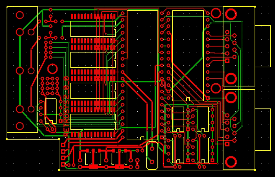
875 x 563 - 327K

Comments
The controllers are fed through a 16:1 MUX (my first time using one) and as such only require a few address lines and a data line to the prop.
The DataFlash ROMs are similar, they share the same Clock, Input and Output lines, but each have their own Chip Select pin connection to the prop as well.
Each of the 1MB EEPROM chips has its own pair of serial lines, so they can be accessed simultaniously.
I left a cutout in the·rear left of the board for the prop clip, it should fit exactly into the notch so the total board is a 3.8 x 2.5" rectangle. I might put a small dab of hot glue or something to keep the clip in place, if needed.
The system as a whole is planned to have its own OS/Menu system for selective loading of programs. At runtime the OS will load up the appropriate program image from DataFLASH to the 32K EEPROM, as well as copy the appropriate Video Texture, and Audio Images to the external 1MB EEPROM banks. It will then trigger a system reset to execute the program.
At the start of every external application, it will re-load the system OS/menu program into the 32K eeprom. When a return-to-system is desired, or if the system is manually reset or shutdown, the system will return to the primary menu application.
I also hope to include the ability to have NetPlay whilst connected to a Internet-enabled PC. The PC would need to be running a 'backburner' application that would trancieve data over the internet, as well as trancieve serial communications through the USB connection to the propeller.
There's alot of software implementation to do here, but I'm starting on it (somewhat)
I plan to purchase the Game programming for the propeller powered Hydra book to serve as a basis for my software design for this system.
Well, I'm off to work, but I hope this explains my concept a bit more,
Post Edited By Moderator (Chris Savage (Parallax)) : 3/7/2007 4:36:58 PM GMT
If anyone has any suggestions on a more custom enclosure solution, please suggest some ideas here!
Post Edited By Moderator (Chris Savage (Parallax)) : 3/7/2007 4:37:07 PM GMT
Looking at your board layout, it looks like the same thing could work - you'd still have access to all the ports and it's clear so people can see inside, but still provides reasonable protection.
You see the retrosys logo in my sig?
I've had the logo since the 1.0 model was developed. I had planned to make a illuminated logo to go on the top panel of the case, but didnt get to it the first time aorund.
I'm planning on it this time. On the back half of the PCB I've got a few LED headers to connect to the lit display, once I get it made.
I plan to get some nice bright blue led's and a red/yellow/green for the leader.
If I simply ethed it into lexan though....hmmm
You've definitially got my gears turning now...
Post Edited By Moderator (Chris Savage (Parallax)) : 3/7/2007 4:37:13 PM GMT
Rgds,
Quattro
▔▔▔▔▔▔▔▔▔▔▔▔▔▔▔▔▔▔▔▔▔▔▔▔
'Necessity is the mother of invention'
▔▔▔▔▔▔▔▔▔▔▔▔▔▔▔▔▔▔▔▔▔▔▔▔
NerdMaster
For
Life
JonnaK: I have a supply setup similar to the Prop Demo board, there's a capacitor or two in there, but I'll keep that in mind, especially if the board seems to be having issues. I havent had experience with ground planes, I'm not too sure how to put them in in the express PCB software, but I'll have to figure that out.
I'm supposed to get in two of these boards today, I'll post a pic and once I get my Prop I'll be able to comment on how its running.
Just out of curiosity, if I do have noise issues, is there any way I could apply my own makeshift ground planing?
I know I probably should have used SRAM instead of EEPROM for runtime memory, but my experience lies in serial communications and EEPROM primarily, so I stuck with what I knew.
Thanks for the feedback! (and the interest!)
Post Edited By Moderator (Chris Savage (Parallax)) : 3/7/2007 4:37:21 PM GMT
Since you are using EEPROM, don't you have a good chance of wearing them out?
How do you plan on loading your data? Your data sets appear to be pretty large, I would guess since you have so much memory.
How much throughput are you getting to/from your main memory?
Thanks,
Doug