

laser ranger-----pity
 kelvin james
Posts: 531
kelvin james
Posts: 531
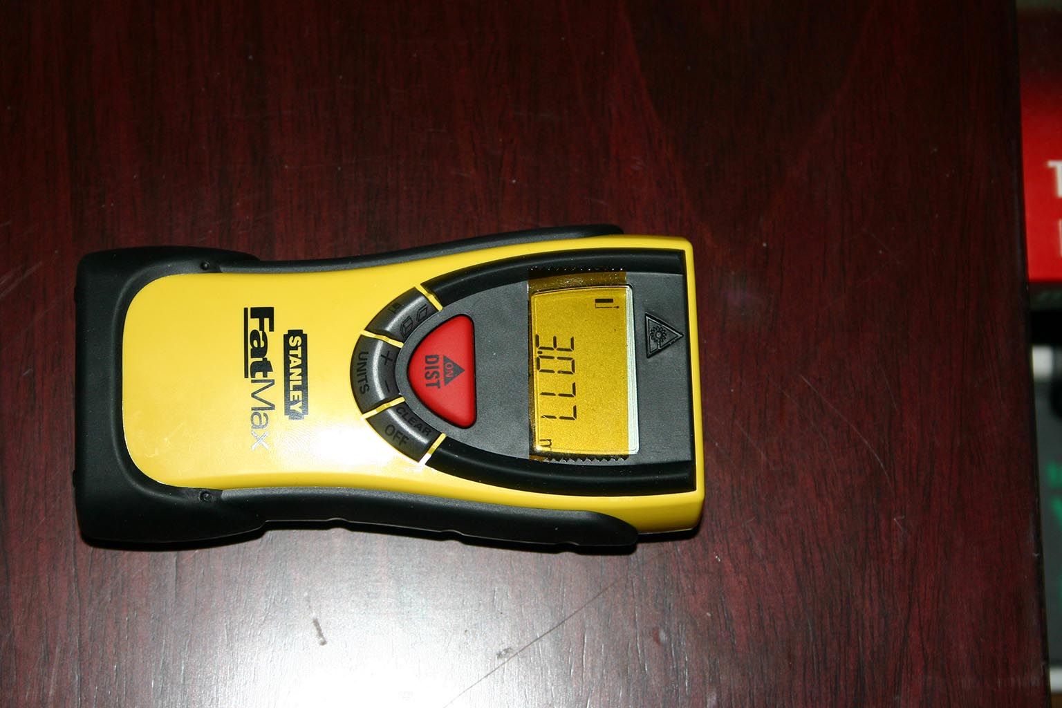
This was an attempt to hack idea with the $100 TLM100 laser ranger
from Stanley, i think cst-berger own it now. The new circuit
technology has made it too much bother to attempt, but i thought i
would share a look inside.
I do quite a bit of handywork, so it will come in useful anyway. I was
hoping this would be an easy way for people to use some laser ranging
technology for their hobby projects, but it looks like the complexity
would be a major deterent. It works very well, specs are 1/4 in.
resolution at 100 ft., i am getting 1/8 in. up to slightly more than
100 ft. with a good read. In metric it displays to the millimeter.
I took it to work to test it against a linear ( 12 ft), and it is very
accurate. It only took a minute to take it apart, obviously no
attempts to hide anything here. The laser send/receive module is
sealed, so no way to see what the inside looks like. My guess is time
of flight for the reading, specs say it has a 1 nanosecond pulse
duration.
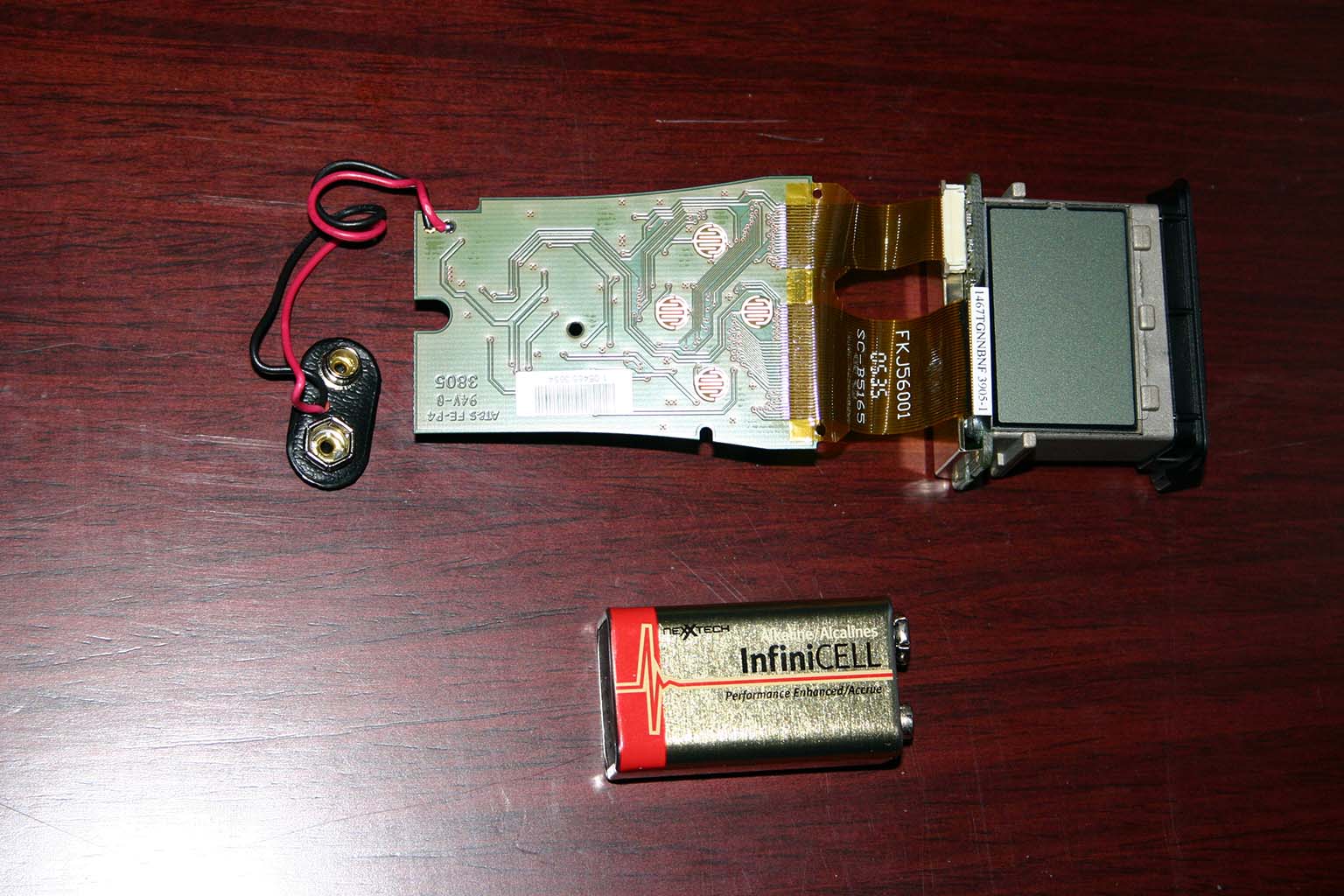
As you can see in the pictures, lots of small smt connections, not
easy play with. The lcd is the major trouble, my guess would be around
150 + segment graphic being used. As far as my eyes can tell, the lcd
has 36 leads, and uses that mylar or whatever strip for cable
connection. I suppose the useful info to the lcd could be probed
easily enough, and decoded to interface with a stamp. But the hardware
interface would be a nightmare.
You will notice the 4 circular circuits on the back of the board,
these are the "switches" for the buttons, good idea, but another
problem to remotely activate.
On the up-side, it does have a microwire serial eeprom on board,
probably to store values when doing volume calculations. It may be
possible to read the write data going to the eeprom, something that i
will look into.
It's a letdown that no one has manufactured a cheap ranger module as
a sensor, though i suppose the patents and other Smile comes into play
here. Even at work i thought of ideas to use this for such things as
error proofing in assembly areas. Anyway, if anyone has any ideas how
to hack this that is non-destructive , i will give it a try.
I would recommend this tool for anyone thinking of purchasing one for
home/work related use. BTW, I bought this from laserstreet.com, good
service. I already tried a search on the part numbers, and nothing
except the eeprom.
from Stanley, i think cst-berger own it now. The new circuit
technology has made it too much bother to attempt, but i thought i
would share a look inside.
I do quite a bit of handywork, so it will come in useful anyway. I was
hoping this would be an easy way for people to use some laser ranging
technology for their hobby projects, but it looks like the complexity
would be a major deterent. It works very well, specs are 1/4 in.
resolution at 100 ft., i am getting 1/8 in. up to slightly more than
100 ft. with a good read. In metric it displays to the millimeter.
I took it to work to test it against a linear ( 12 ft), and it is very
accurate. It only took a minute to take it apart, obviously no
attempts to hide anything here. The laser send/receive module is
sealed, so no way to see what the inside looks like. My guess is time
of flight for the reading, specs say it has a 1 nanosecond pulse
duration.
As you can see in the pictures, lots of small smt connections, not
easy play with. The lcd is the major trouble, my guess would be around
150 + segment graphic being used. As far as my eyes can tell, the lcd
has 36 leads, and uses that mylar or whatever strip for cable
connection. I suppose the useful info to the lcd could be probed
easily enough, and decoded to interface with a stamp. But the hardware
interface would be a nightmare.
You will notice the 4 circular circuits on the back of the board,
these are the "switches" for the buttons, good idea, but another
problem to remotely activate.
On the up-side, it does have a microwire serial eeprom on board,
probably to store values when doing volume calculations. It may be
possible to read the write data going to the eeprom, something that i
will look into.
It's a letdown that no one has manufactured a cheap ranger module as
a sensor, though i suppose the patents and other Smile comes into play
here. Even at work i thought of ideas to use this for such things as
error proofing in assembly areas. Anyway, if anyone has any ideas how
to hack this that is non-destructive , i will give it a try.
I would recommend this tool for anyone thinking of purchasing one for
home/work related use. BTW, I bought this from laserstreet.com, good
service. I already tried a search on the part numbers, and nothing
except the eeprom.
Comments
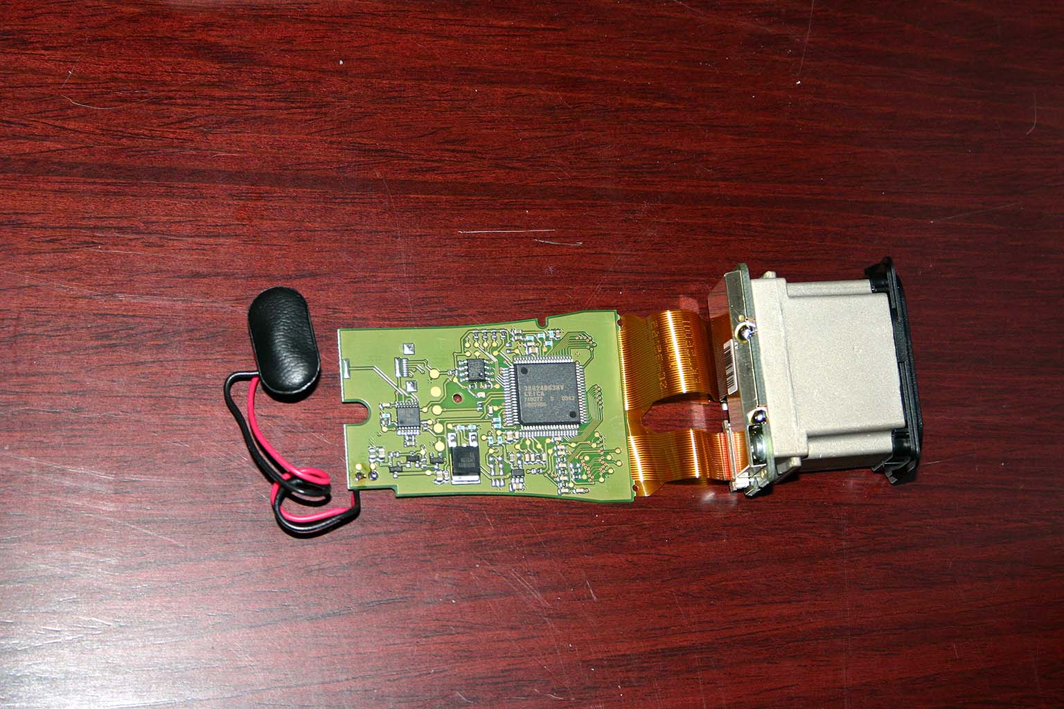
The large chip has the word 'LEICA' on it, and they doesn't just sell camera lenses, but also some very expensive surveying equipment, so it's a good bet that it is the 'brains' in this setup.
Now, $100 sounds cheap for a laser rangefinder.
Are you certain that this IS a laser rangefinder?
Some only use the laser as a pointer, and does the actual measuring with ultrasonics...
(A picture of the end would help for that)
▔▔▔▔▔▔▔▔▔▔▔▔▔▔▔▔▔▔▔▔▔▔▔▔
Don't visit my new website...
The Leica's I have purchased in North America ran about $300 for a true time-of-flight laser ranger.
I made an interface with an SX52 to selected display segments, those were all being clocked at 1 mHz as I recall. Quite a bit of trickery capturing the desired segments .... there were tons (256?) of them, and then mapping those into a table to generate machine readable distances. Ended up working pretty well. As I recall, the actual measuring accuracy was a pretty impressive 1 mm in 30 ft.
Cheers,
Peter (pjv)
Yup, she's a real laser range finder, you can shoot this through a keyhole and get a reading, can't do that with sonic, not to mention the 100 ft. range. Leica makes these for Stanley/ Berger whoever, they own the the rights to the technology. The TLM100 is the base model, there is the 200 and 300 also, with higher range and resolution. The time of flight is not magic, if you want some good info, look at the acam website for the TDC chip ( time to digital convertor ). It would not suprise me that they manufacture the chips for Leica. The laser module itself is the mystery to the workings, like a beam splitter for a comparator. I figure trying to do a shift-in from the eeprom data line will give the necessary info, but i have to figure out the configurable bit length, and toss the other address data, etc. The eeprom is made by CSI, a 1 mhz 1K serial, data sheet included below. Having to remotely control the swiches without hardware is a problem. I think the keypad is a conductive material that activates the circuit on the board, pictures included. Attemping to read the lcd data is not going to happen here. For obvious reasons, there is no commercial aspect here other than trying to get an external reading from the unit, to use for hobbiest purposes. Mine came with laser safe glasses, hint---hint.
Looks to have a few test points on the pcb for calibration or programming?
The Leica chip could be an asic, of the 5 large pads, 1 is ground 2 go into the Leica chip, not sure where the other 2 pins go.
There looks to be an interesting non populated connector in the corner, wonder what it's for?
Gavin
Did a quick google
http://www.ja-gps.com.au/leica_rangefinder.html
Looks like Leica do a few laser range finders.
http://www.lascolaser.com/show_products.php?cat=Hand Held Distance Meter
The Stanley one looks like the cheapest.
Good find find Kelvin, I can remember when the TI Ultrasonic modules first came out, very soon robots everywhere were using them.
Gavin
Very interesting indeed. It will be great when you can get usable data out of it!
What's the latest?
Any progress?
fish
And yes it does all the calculations... It also seem to be a LCD driver, not exactly one, but I can't figure out any other ICs...
What I want to point out is that the "head" of the device is probably a stand alone sensor which has it's one IC...
As you can see there is a magnetic GND shield in the back of the sensor... And this is where all the electronics are...
By·seeing the width of the connector (this brown cable - leaf like thing) I can say that it is connected in parallel with the microcontroller...
Probably there are trigger and chip select connections... You won't be able to know until you get the .pdf from the producer of the product or the company which made the sensor if you can fing any readings on the sensor...
Just get to know which sensor is and download the .pdf!!!
Do that and we will be able to help you further...
Friendly advice,
Lefteris Greece...
▔▔▔▔▔▔▔▔▔▔▔▔▔▔▔▔▔▔▔▔▔▔▔▔
-Rule your Destiny-
--Be Good. Be Bad. Be Provas--
The hellinic (Greek) robots portal: Greekbotics
Many Projects and Schematics by the users·and also robotic news
(Translate using babelfish)
Shielding would be to protect the sensitive amp from noise?
Just a guess from I design I did a very long time ago, back when red laser diodes were $300 each.
Gavin
Here is a laser range finder that has a RS232 interface http://www.opti-logic.com/industrial_rangefinders.htm
its a little pricey at 500 dollars but is a real nice unit.
Would you mine taking Higher Quality Pictures of the Front and Back PCB and possible all the chip numbers from each chip.
If you have time to do this thanks,
Chris
1 - 4v power I think
2 - looks low
3 - low, has gnd plain
4 - 3.4v 5.0 mhz afte shot, 10mhz before shot
5 - 10mhz before shote, 5mhz after. ac coupled 200mv or so
6 - 50 uS low-going pulse on trigger
7 - looks like serial clock pulses - 24 pulses multiple times during measurement
8 - gnd i think - connected to pin 3
9 - looks like serial data pulses
10 - seven pulses, 12.5ms long at 50ms intervals
11 - looks like constant 1 volt
12 - 18 pulses 2.3ms long, about 4ms apart. missing pulse after pulse 2
13 - 3.6v whenever power is on
14 - 3.36 v normally, but dips very slightly, apparently as the unit seeks distance
15 - powers up during measurement, powers down with slight decay after more or less 1/2 second
16 - gnd
17 - complicated - initial pulse from 1.7 up to 3.6, then series of 7 up down spikes
18 - even more complicated
pins 7 and 9 look very promising to me. I haven't had time to investigate them further. Maybe one of you can look into it.
Been scowering the interenet now for over an hour looking for a really cheap 1 point laser rangefinder that can be interfaced with. It is so ridiculous that this is so hard.
I am a ME working for GDRS. I am used to high quality ladars at work, and just want something cheap at home.
Anyways
Good luck getting the info from the eeprom, really hope you figure it out and spread the knowledge.
Will post back if i ever find something this cheap but easier.
Right now, i have my sights set on finishing a sun tracker system. After that, when i finally take the plunge for a good digital scope, i will work on the tlm. I have wanted to do this so the robotics community would have a cheap ranger to use.
By the way, this is one of the few companies that sell oem laser ranger components, i have never bought from them, so i can't give any recommendation.
http://www.eodevices.com/main_home_frameset.htm
Post Edited (kelvin james) : 7/27/2008 4:02:23 PM GMT
http://www.acroname.com/robotics/info/articles/sharp/sharp.html#e8
I was originally not paying attention to IR sensors.
But sharp claims these will work outside in full sun looking at a black target.
While its not true time of flight, if it works how they say, I might be able to use this.
Lucas
http://www.crustcrawler.com/code/index.php?prod=20
Did you or anyone else ever get anywhere with this laser finder? Sounded like you were making progress and then the thread stops.
If you need any help, I am retired and do this stuff 12 hrs a day in my lab.
Earl
This interface board provides a USB port for a Fluke 411D which is the same basic laser distance meter as the Stanley TLM100.
Has there been any further progress in hacking into the Stanley TLM-100?
Thanks
-Ben