

NEW 40-pin Propeller prototype module - Most hackable yet?
 RobotWorkshop
Posts: 2,307
RobotWorkshop
Posts: 2,307
Hello,
For new designs the standard for the 40-pin propeller modules (like the PropStick) seems to be a pin configuration like the 40-pin DIP propeller chip. This is cool for new things but I though it might be nice to also have one that has a pinout like the BS2p40 modules (and also my SX48 40-pin module). This would help for existing designs where someone may want to try out the propeller without altering their board.
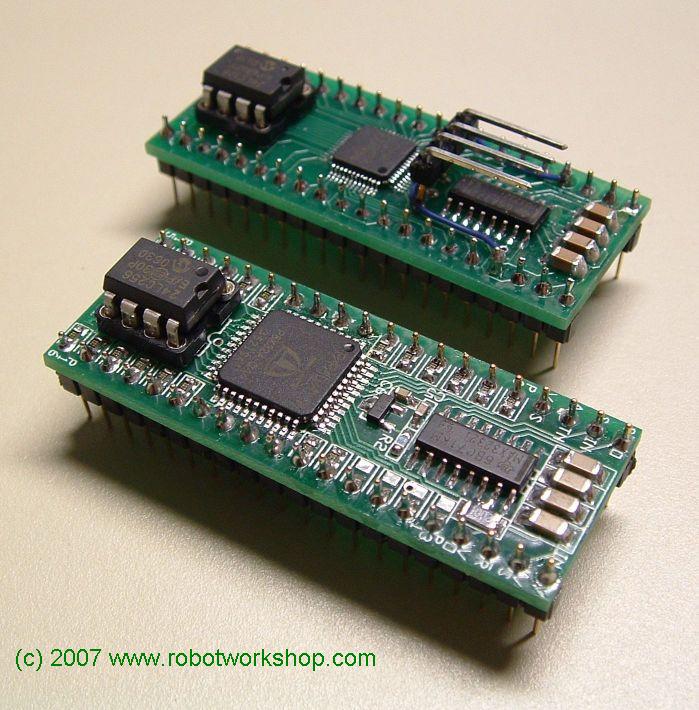
For those of you that have been watching the SX forum you may have spotted a new 40-pin SX48 module I recently made. I was pleased with the way the SX48 prototype and while waiting for the final boards to come in for that I thought I would try to do something similar for the Propeller. I was able to reuse some of what I had done on the SX48 board but it was a tight fit to squeeze the propeller and extras all on the tiny board. It was a stretch for me and definitely pushed my into a new area. No auto-routing or anything. I did this manually as I really had to work to get it right. I think the effort was worth it!
It has an on-board 3.3v regulator, 5mhz xtal, 32K socketed EEPROM, and max3232 chip w/reset wired so the same Serial cable I use for programming the BS2p40 module works! So, the first 4 pins and the last 4 pins on the module work the same as a BS2p40 and the SX48 40-pin module. Any one of the three can now be interchanged in the same 40-pin socket (or circuit wired on a breadboard). Programming is the same on the BS2p40 and the prop which can both use the same wiring and cable. The SX48 uses this cable as a serial port and needs a SX-Key or SX-Blitz to program. The only sticking point is if peripherals expect +5v from the modules they get that from the BS2p40 and SX48 but this new Prop module only puts out 3.3v. I almost tried to squeeze a 5v regulator on their too and may if I make any more of these and it make sense to do so.
I just got the sample board in this evening and have just finished soldering the little rascal up (the board is still warm). I felt like a watch maker building the thing and it was definitely tricky to solder some of the smaller parts (down to 0603) that I had to use. Not something for everyone as a steady hand and good eyesight (or a huge magnifier) is needed for many parts. This new module can be assembled in a variety of ways though. All of the pins P0-P31 for the ports are configurable and can be left open, bridged closed, have a resistor, or cap. The sample has all 1K resistors (pin P28-P31 open) at the moment but I suppose I could have used the appropriate values to connect to a VGA monitor directly.
It is definitely a tricky little thing to assemble but this was just with a regular fine tip weller soldering iron, some solder wick, a really good set of tweezers, and a lot of patience. I think the SX48 module can work as a kit and may try something with this if that works out ok.
There are quite a few cool things going on with the propeller and what others have been doing. I am amazed at what is being written for this chip (man there are some bright people on this group!) and now that i'm a bit more familiar with the hardware hope to catch up on the software side.
Hopefully this module will be one more cool thing to add to the list. It's something i'm proud of and after getting it together am still (pleasantly) surprised that I pulled it off and the first time I plugged it in the software found the propeller! I guess the trials of first building a demo circuit on a protoboard (which did not work the first or second time) and getting the reset circuit to work like the stamp paid off. This weekend i'll try to beat this new module up a bit and make sure the rest of it works as expected.
Anyway, if you have comments or suggestions for improvements i'd love to hear about it.....
Best Regards,
Robert
For new designs the standard for the 40-pin propeller modules (like the PropStick) seems to be a pin configuration like the 40-pin DIP propeller chip. This is cool for new things but I though it might be nice to also have one that has a pinout like the BS2p40 modules (and also my SX48 40-pin module). This would help for existing designs where someone may want to try out the propeller without altering their board.
For those of you that have been watching the SX forum you may have spotted a new 40-pin SX48 module I recently made. I was pleased with the way the SX48 prototype and while waiting for the final boards to come in for that I thought I would try to do something similar for the Propeller. I was able to reuse some of what I had done on the SX48 board but it was a tight fit to squeeze the propeller and extras all on the tiny board. It was a stretch for me and definitely pushed my into a new area. No auto-routing or anything. I did this manually as I really had to work to get it right. I think the effort was worth it!
It has an on-board 3.3v regulator, 5mhz xtal, 32K socketed EEPROM, and max3232 chip w/reset wired so the same Serial cable I use for programming the BS2p40 module works! So, the first 4 pins and the last 4 pins on the module work the same as a BS2p40 and the SX48 40-pin module. Any one of the three can now be interchanged in the same 40-pin socket (or circuit wired on a breadboard). Programming is the same on the BS2p40 and the prop which can both use the same wiring and cable. The SX48 uses this cable as a serial port and needs a SX-Key or SX-Blitz to program. The only sticking point is if peripherals expect +5v from the modules they get that from the BS2p40 and SX48 but this new Prop module only puts out 3.3v. I almost tried to squeeze a 5v regulator on their too and may if I make any more of these and it make sense to do so.
I just got the sample board in this evening and have just finished soldering the little rascal up (the board is still warm). I felt like a watch maker building the thing and it was definitely tricky to solder some of the smaller parts (down to 0603) that I had to use. Not something for everyone as a steady hand and good eyesight (or a huge magnifier) is needed for many parts. This new module can be assembled in a variety of ways though. All of the pins P0-P31 for the ports are configurable and can be left open, bridged closed, have a resistor, or cap. The sample has all 1K resistors (pin P28-P31 open) at the moment but I suppose I could have used the appropriate values to connect to a VGA monitor directly.
It is definitely a tricky little thing to assemble but this was just with a regular fine tip weller soldering iron, some solder wick, a really good set of tweezers, and a lot of patience. I think the SX48 module can work as a kit and may try something with this if that works out ok.
There are quite a few cool things going on with the propeller and what others have been doing. I am amazed at what is being written for this chip (man there are some bright people on this group!) and now that i'm a bit more familiar with the hardware hope to catch up on the software side.
Hopefully this module will be one more cool thing to add to the list. It's something i'm proud of and after getting it together am still (pleasantly) surprised that I pulled it off and the first time I plugged it in the software found the propeller! I guess the trials of first building a demo circuit on a protoboard (which did not work the first or second time) and getting the reset circuit to work like the stamp paid off. This weekend i'll try to beat this new module up a bit and make sure the rest of it works as expected.
Anyway, if you have comments or suggestions for improvements i'd love to hear about it.....
Best Regards,
Robert
699 x 710 - 104K
Comments
Does the board perform well in a high speed data envoronment with LC interference?
▔▔▔▔▔▔▔▔▔▔▔▔▔▔▔▔▔▔▔▔▔▔▔▔
Definetly a E3 (Electronics Engineer Extrodinare!)
"I laugh in the face of imposible,... not because i know it all, ... but because I don't know well enough!"
The protection for each I/O pin depends upon how it is assembled. As I mentioned each I/O pin has a small set of pads that can be left open, solder bridged, or can have a resistor. At the moment the protection is with a 1K resistor as one recommendation in the pinned topic on how to safely interface 5v logic to the propeller. There isn't enough space left for any other buffers as the underside of the board is also populated with the crystal, voltage regulator, and a variety of other stuff. This could also be used in a 3.3v circuit and in that case the buffers wouldn't be needed. That's what I meant by the "Hackable" in the title. Each I/O can be customized..
Even though there is definitely some things to plan out for each I/O pin and how it should be assembled, I just like that the pin layout matches the old standard 40-pin stamp layout and that it doesn't need a prop clip or anything special for programming.
I have enough parts to build a second module and am going to use a 6Mhz crystal instead and just bridge some of the I/O pads to build it as more of a 3.3v module. I expect this should work after reading other posts that the prop should run ok with this and internally will be clocked at 96Mhz. I'll let everyone know how that turns out.
At the moment none of the projects I have are using any sort of high-speed LC circuits so I haven't been looking at that or have a way to test that at the moment. If you have any examples of a test circuit for that and some prop code (i'm still brushing up on coding for the prop) I would certainly give it a shot.
For now, this is a prototype and I don't have any extra for sale. I'm going to keep on working on this and see if it needs any other refinements. If there is enough interest I can see about getting some more boards and perhaps a kit as well.
Best Regards,
Robert
--Paul
crgwbr
▔▔▔▔▔▔▔▔▔▔▔▔▔▔▔▔▔▔▔▔▔▔▔▔
NerdMaster
For
Life
I don't have any plans to do anything with a 24-pin size module and will leave that to Parallax or others to do. I expect it would have to use the QFN package and I have no idea how i'd solder one of those packages on!
For the moment i'm just sticking with the 40-pin form factor for all my projects that would use a stamp, SX48, or propeller. This new propeller module and the SX48 module fill a small niche and are complimentary to what Parallax and others are currently offering. I think these could make cool little kits and would rather go that route since I want to brush up on the software side and use some of these in projects instead of sitting and soldering a bunch of new modules up. Anyway, this was a fun project and now I want to play with making them do some cool stuff.
I had enough parts to build a second module this afternoon which is now running a 6Mhz crystal (96Mhz internal) and so far things look good. Just need to update the board (to tie WP low) and perhaps in a few weeks will build up a couple more of these to make sure the board design is perfect.
Best Regards,
Robert
Charlie
Robert
Paul
▔▔▔▔▔▔▔▔▔▔▔▔▔▔▔▔▔▔▔▔▔▔▔▔
'Necessity is the mother of invention'
▔▔▔▔▔▔▔▔▔▔▔▔▔▔▔▔▔▔▔▔▔▔▔▔
Paul Baker
Propeller Applications Engineer
Parallax, Inc.
Thanks for that. Input levels 3.3v ? - just wondering if input levels will have to be adjusted on some of my existing custom boards ? Before I offer customer upgrades ! Any quick reference pdf yet? Projected Launch date or price range - sorry this has perked my interest ..
Quattro
▔▔▔▔▔▔▔▔▔▔▔▔▔▔▔▔▔▔▔▔▔▔▔▔
'Necessity is the mother of invention'
▔▔▔▔▔▔▔▔▔▔▔▔▔▔▔▔▔▔▔▔▔▔▔▔
Paul Baker
Propeller Applications Engineer
Parallax, Inc.
Thanks for that - was kind of hoping that I/O's would have been compatible with stamp 5v so as to facilitate 'Direct Replacement' in current stamp based designs perhaps by inclusion of series resistor / zener diode on inputs with transistors on outputs to facilitate 'switching out' the onboard 5v (as I believe there is an onboard 5v reg as well as the 3.3v reg) - design seems to be well past that possibility now though - all the same its nice to dream..
Again - many thanks for the reply..
▔▔▔▔▔▔▔▔▔▔▔▔▔▔▔▔▔▔▔▔▔▔▔▔
'Necessity is the mother of invention'
Post Edited (QuattroRS4) : 2/20/2007 6:02:07 AM GMT
▔▔▔▔▔▔▔▔▔▔▔▔▔▔▔▔▔▔▔▔▔▔▔▔
Paul Baker
Propeller Applications Engineer
Parallax, Inc.
▔▔▔▔▔▔▔▔▔▔▔▔▔▔▔▔▔▔▔▔▔▔▔▔
'Necessity is the mother of invention'
▔▔▔▔▔▔▔▔▔▔▔▔▔▔▔▔▔▔▔▔▔▔▔▔
Paul Baker
Propeller Applications Engineer
Parallax, Inc.
▔▔▔▔▔▔▔▔▔▔▔▔▔▔▔▔▔▔▔▔▔▔▔▔
'Necessity is the mother of invention'
(the other Paul)
▔▔▔▔▔▔▔▔▔▔▔▔▔▔▔▔▔▔▔▔▔▔▔▔
Paul Baker
Propeller Applications Engineer
Parallax, Inc.
It would be an easy change to make but would add to the width of the finished module. At the moment it is .77 inches wide overall. Either that or leave it as is and just stand up a pull-up resistor vertically next to the I/O pin and just solder a wire across the top of any pull-up resistors present to one of the supply lines. It would sure make an interesting looking module!
So far the testing is going well and just want to see if I should try and cram anything else on there before making any more prototypes.
Best Regards,
Robert
Why use discrete components?
Why do not use standard RS-232 port instead of that USB dongle?
Why dont use a 128k eeprom?
·
- Leaving that I/O pin completely disconnected (as in the case of P28, P29, P30, and P31)
- Just solder bridge the connection if the output is going to go to other 3.3v logic or something that doesn't warrant using an inline resistor for protection
- Any resistor can be used. If the same resistors are installed as needed by the VGA output that will allow the module to be directly connected to a VGA cable or connector. Other values can be used for different needs.
- A small cap could be used instead at the I/O pin if the application needs it.
I like being able to make it any way I like!
The 40-pin module doesn't require any USB dongle, Propclip, etc. It has a MAX3232 onboard and is wired so that it can use an existing BASIC Stamp type connection to the Host. On my breadboard for testing I have a DB-9 connection back to the host PC. I can interchange a BS2p40 or this 40-pin prop module without any other wiring changes and can program either one with the same serial cable. It's reset circuitry on the module compensates so it acts more like that of the Stamp (at least from the wiring of the programming cable)
This module also has an 8-pin DIP socket so that larger EEPROM's should also be able to plug right in.
At the moment this is just a prototype but if there is enough interest I could probably make boards available with instructions on how to build them. It takes excellent soldering skills and a steady hand to build and they are not suitable for everyone.
Robert
I was looking at some old posts
'
How did this turn out?
'
Do you have any more of this little boards?