TTL vs. CMOS inputs?
Hi all -
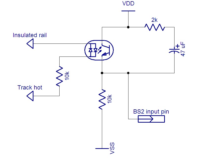
I am using a BS2 to automate some functions of an AC-powered model railroad. I am using a circuit (see attachment) with an AC optocoupler to detect the presence of the train; the train wheels complete an AC circuit which turns on the optocoupler. I connect the transistor end of the optocoupler to a BS2 pin. Because the AC signal is very noisy (intermittent contact between track and wheels), I have a 47uf capacitor (in series with a 2k resistor) across the optocoupler output to smooth/debounce the signal.
This circuit works very well when the outputs are connected directly to the Stamp. I tried connecting the outputs to a SN74HC165 shift register instead, to see if I could conserve input pins. Operation is a little erratic with the shift register - the signal goes low from time to time when it would stay high if directly connected to the Stamp pin.
I am wondering if this is a CMOS v. TTL voltage issue? The optocoupler is described as "transistor output" which I am assuming equates to TTL, and from what I gather the BS2 is a TTL input. The SN74HC165 is a CMOS device though. Is it possible that the problem is hooking a TTL output to a CMOS input? Could I solve it by using a TTL version of the shift register?
Thanks for your thoughts.


Comments
One issue with filtering the LED side is that I have several of these circuits together, using 4-channel optocouplers. It would be kind of bulky to have 8 or 16 bridge rectifiers stuck in.