

Big Troubles with StickBoard & ServoControl ((2) old Post look downside)
 nomad
Posts: 276
nomad
Posts: 276
hi,
excuse the new thread.....
thanks for the answer,
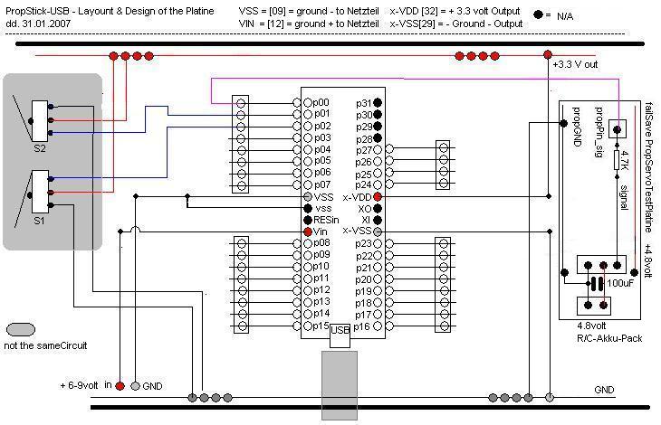
first: as attachment i upload the newest pic from my propstick-motherBoard with the
······ 2-Buttons-circuit and the Servo-Circuit.
······ = servoTestBoard_New.jpg
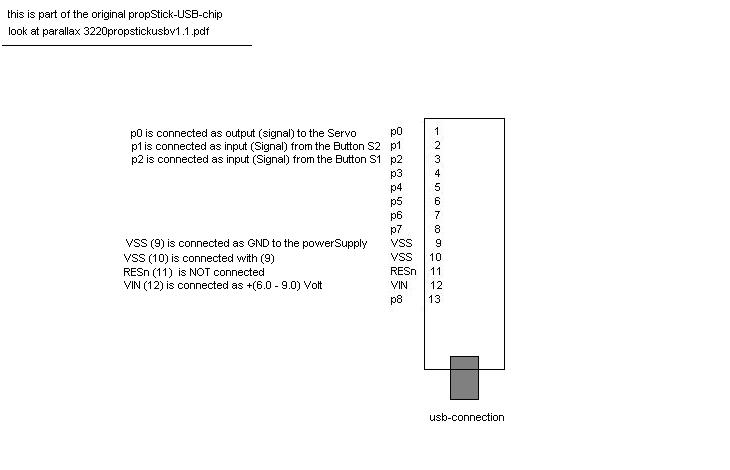
second: as attachment i upload a clipping from originalStickBoard.jpg
······· - the name of the pdf-file is: 3220propstickusbv.1.pdf
······· !!!! are the Connection (VSS(9), VSS(10), RESn(11), VIN(12)·· correct????·
it's possible, that somebody have correct-schematics of a stick-chip and the motherboard?
yesterday in the evening, i have a idea:
with the PropDem-Board - Packages was included a
- original usa-power-supply
· Datas: Voltage: 6.0 to 7.5volt
········ Ampere : 6.0 with 2.0 A
········ Ampere : 2.15 to 1.7A
in switzerland we have a another power-system, so my distributor delievered
a power-supply for my country.
- my power-supply
· - Datas: Voltage: 3.0, 4.5, 6.0, 7.5 9.0, 12.0 volsts
·········· Ampere : 1000 mA
its possible that my power-supply dont have enough ampere
parallax wrote input-power should be 6 to 9 volt
and i think when the usa-power-supply delieverd 1.7A with 7.5volts
then delievered my power-supply too low amperes. (< 1.0Ampere)
is this eventually the fault.???
on the weekend: i tests with parallax-educations-stuff (LEDs & buttons) with
the DemoBoard and the stick-board.
for every assistance and help, i am verry,verry happy.
Attachments: - originalStickBoard (part of)
·················· - servoTestBoard_New.jpg
·················· - simpleServoStick1.spin
Greetings
nomad
excuse the new thread.....
thanks for the answer,
first: as attachment i upload the newest pic from my propstick-motherBoard with the
······ 2-Buttons-circuit and the Servo-Circuit.
······ = servoTestBoard_New.jpg
second: as attachment i upload a clipping from originalStickBoard.jpg
······· - the name of the pdf-file is: 3220propstickusbv.1.pdf
······· !!!! are the Connection (VSS(9), VSS(10), RESn(11), VIN(12)·· correct????·
it's possible, that somebody have correct-schematics of a stick-chip and the motherboard?
yesterday in the evening, i have a idea:
with the PropDem-Board - Packages was included a
- original usa-power-supply
· Datas: Voltage: 6.0 to 7.5volt
········ Ampere : 6.0 with 2.0 A
········ Ampere : 2.15 to 1.7A
in switzerland we have a another power-system, so my distributor delievered
a power-supply for my country.
- my power-supply
· - Datas: Voltage: 3.0, 4.5, 6.0, 7.5 9.0, 12.0 volsts
·········· Ampere : 1000 mA
its possible that my power-supply dont have enough ampere
parallax wrote input-power should be 6 to 9 volt
and i think when the usa-power-supply delieverd 1.7A with 7.5volts
then delievered my power-supply too low amperes. (< 1.0Ampere)
is this eventually the fault.???
on the weekend: i tests with parallax-educations-stuff (LEDs & buttons) with
the DemoBoard and the stick-board.
for every assistance and help, i am verry,verry happy.
Attachments: - originalStickBoard (part of)
·················· - servoTestBoard_New.jpg
·················· - simpleServoStick1.spin
Greetings
nomad
730 x 470 - 69K
730 x 470 - 28K

Comments
The program is working well with my test board. A power supply of 1A is enough for a 'ordinary' servo about ~4 kg-cm / ~50oz-in or a few more specialy free of load.
Are you well checked all you connections because your schematik look right.
Take card about the connection of the servo, in your schematic, the connection is 'Ground, +5v, Signal' and in the spin, you draw '+5v, Ground, signal'
What happen exactly when you power on ?
dro.
▔▔▔▔▔▔▔▔▔▔▔▔▔▔▔▔▔▔▔▔▔▔▔▔
in medio virtus
Post Edited (inservi) : 2/10/2007 11:00:50 AM GMT
reply: What happen exactly when you power on ?
······· == nothing
reply: Take card about the connection of the servo, in your schematic,·the· connection is 'Ground,
······ +5v, Signal' and in the spin, you draw '+5v, Ground, signal'
······ == i not understand you,
······ == the servo signal goes to PropStick p0 as signal
········· the servo gnd - have common ground with the board
···························· - and goes to the R/C AccuPack (4.8volt)
······ == this circuit is running with the PropDemoBoard
········· changes are p5 insteed of p0
now i making some tests:
Tests & Troubleshuting PropellerStickUSB dd. 10.02.2007
1. Important: i have first testing the PropellerDemoBoard:
············· - power-supply = 9volt·········· (from my distributor)
············· - program····· = LedOnOffP5.spin
············· - schematics·· = p5 as output -> 100ohm -> +LED - ---- VSS
···············
············· - result······ = 1.first Test with DemoBoard == OK led blinking
2. Important: now i test the PropStickUSB-Chip with my motherBoard
············· - power on 9volt = no load = 13.04 (ampere ??)
············· - power-supply = 9volt· (from my distributor)
············· - program····· = LedOnOffPx.spin
············· - pins········ = Px = p0 on the chip (leftUp)
············· - schematics·· = P0 -> 100ohm(red,red,brown,gold) -> + LED - ---> VSS
···
·· results: - on PropStick Pin 32 (VDD) = + 3.35volt
·························· Pin 29 (VSS) = gnd····
··········· - with F7 = comport found
··········
··········· - led_blinking on pin0 Supper
··········· - now i reduce the frequence of the ledblinking with:
············· - waitcnt(500_000 + cnt)
··········· - result led blinking verry fast ok
3. now i test all pins with this program: same detail as above
·· results : p0· - p7· all ok (verry fast & verry slow 50_000_000)· = OK
············ p8· - p15 all ok· "
············ p16 - p23 all ok
············ p24 - p27 all ok
············ p28 - p32 not used
··
4. now i simulate the-servo-Test with:
·· - p0 is a LED_1 with a frequence of = waitcnt(10_000_000 + cnt)
·· - p1 is a LED_2 with a frequence of = waitcnt(500_000 + cnt)
·· - p2 is the Button S1 control the LED_1
·· - p3 is the button S2 control the LED_2·····
·· - button-circuit: as my servoTestBoard_NEW.jpg
·· - schematics = P0 -> 100ohm(red,red,brown,gold) -> + LED_1 - ---> VSS
······ ············· = P1 -> 100ohm(red,red,brown,gold) -> + LED_2 - ---> VSS
···· s1· pin 1 = gnd····· -> 4.7K ->· to board VSS (p29)
········· pin 2 = +3.3volt··· ······ ->· to board VDD (p32)
········· pin 3 = signal··········· ·· ->· to boardPin p2
···· S2··pin 3 = signal·········· -> to boardPin p3
········· pin 2 = +3.3volt->··· ·-> to board VDD (p32)
········· pin 1 = gnd -> 4.7K·· -> to Board VSS (p29)
·· - look at simulateServo1.spin
·· - running on PropStickUSB OK
i send you my results, please have a look
i have no idea whats going wrong???
should my simpleServoStick1.spin running.
is this a software or a timing problem??
on the evening or tomorow morning, perhaps i make a new test with the servo
greetings
nomad
attachments: LedOnOffPx.spin
·············· ··· simulateServo1.spin
by " Take care about the connection of the servo, in your schematic, the connection is 'Ground,
+5v, Signal' and in the spin, you draw '+5v, Ground, signal' "
i want say that you must be shure to connect the servo corectly.
All servo have not the same pinout.
In your schematic, you use this
             +-+
    ground   |o|
       +5v   |o|
    Signal   |o|
             +-+
In the spin simpleServoStick1.spin you describe :
                             +--------------------------+
       5V  ?-----------------¦ 5V                       ¦
                  ? 2200µF   ¦        Modellbauservo    ¦
      GND  ?-----------------¦ GND                      ¦
                             ¦                          ¦
    Pin0   ?------??---------¦ Pulse                    ¦
                  4K7        +--------------------------+


or :
             +-+
       +5v   |o|
    ground   |o|
    Signal   |o|
             +-+
That is 2 different connections pinout. Be shure to use the good one.
dro
▔▔▔▔▔▔▔▔▔▔▔▔▔▔▔▔▔▔▔▔▔▔▔▔
in medio virtus
Post Edited (inservi) : 2/10/2007 3:20:36 PM GMT
this is a another servo:
my servo-connections are:
··· ···················· +-+
····yellow signal····|o|
····red·· +4.8V···· ·|o|
····black ground· ··|o|
························ +-+
with the PropellerDemoBoard the circuit is OK and the Servo is running.
greetings
nomad