

an 'LED' 5 x 7 matrix - (SX) - how do I form letters ?
 tommy
Posts: 84
tommy
Posts: 84
. I was hi-jacking someone's thread - and would like to start here, especially so that the title might better match...
. previous multiple (more than 20) LED discussion was mostly about power distribution using (25%) duty-cycle so as to not overload the SX.··there was little discussion about lighting certain LEDS simultaneously (or quickly one after the other to fool the eye).
The blood bank has a date posted in crayon, (56 days in advance) when a donor might visit again, and I bought three of these modules thinking that I might be able to (keep track of time and) spell·the month of the year, as in JAN, FEB, etc...··· but in the 5 x 7 matrix, using two leads of just power and ground, only one pixel could be lit at a time...·· Theory first, please:· things like duty-cycle and figuring out the letter-patterns should I wish to spell a word...
·
.·later on there'll be cascading of the patterns to make moving words, I guess - but not yet, please -- I would be very happy now to be able to make a letter in each 5 x 7 matrix.···---·· right now I can see getting one, vertical row at a time, lit in the pattern I would like - that would be a duty cycle of 20% across the width of the first letter...
. but now I'd like more letters.··· is there a chip for this ?
Post Edited (tommy) : 2/7/2007 6:32:15 PM GMT
. previous multiple (more than 20) LED discussion was mostly about power distribution using (25%) duty-cycle so as to not overload the SX.··there was little discussion about lighting certain LEDS simultaneously (or quickly one after the other to fool the eye).
The blood bank has a date posted in crayon, (56 days in advance) when a donor might visit again, and I bought three of these modules thinking that I might be able to (keep track of time and) spell·the month of the year, as in JAN, FEB, etc...··· but in the 5 x 7 matrix, using two leads of just power and ground, only one pixel could be lit at a time...·· Theory first, please:· things like duty-cycle and figuring out the letter-patterns should I wish to spell a word...
·
.·later on there'll be cascading of the patterns to make moving words, I guess - but not yet, please -- I would be very happy now to be able to make a letter in each 5 x 7 matrix.···---·· right now I can see getting one, vertical row at a time, lit in the pattern I would like - that would be a duty cycle of 20% across the width of the first letter...
. but now I'd like more letters.··· is there a chip for this ?
tommy
Post Edited (tommy) : 2/7/2007 6:32:15 PM GMT
300 x 350 - 19K
Comments
In the other thread PJ Allen directed you to thread:
http://forums.parallax.com/forums/default.aspx?f=7&m=162118
and you indicated you had read -and hopefully understood- the contents.
In my post there on Dec 26, I show and attached the code for an SX28 running a clock program for a 4 digit 7 segment (7x4 matrix) LED display. If you connect your display which I think is not a 7 segment, but a 5x7 dot matrix, to the SX pins indicated it will light up the segments as if it were a 7 segment display.
To drive a single digit (letter) of your display, you will have to extend my code to become 5 columns instead of 4, and modify the dot lookup table to accommodate all the combinations you require. If you can live with numbers only, it's not too bad, but if you also want letters, and possibly graphics characters, it get much more complicated.
So why not just try the numbers and see what you get ?
Cheers,
Peter (pjv)
Post Edited (pjv) : 2/7/2007 7:29:39 PM GMT
·. well, okay...· I thought that there might be some sort of hidden magic that would cause a fella to invent a display wired in this manner.· I'm not worried about writing illumination schemes - much of my MS-DOS assembly language work consisted of a (keyboard only) drawing program - there were schemes galore while looking at all of that upper memory through a one-segment window...
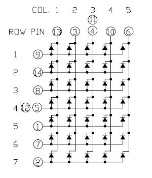
·. but how about the example below.· I might latch the rows across (freeing up computer pins) then use fifteen pins to illuminate the vertical·columns, one pattern at a time...· (all of the 1's, first, all of the 2's second, etc...)
·
.·in the above sample - doing each of the six patterns consecutively would end up with a 16% duty cycle.
. . . would it flicker ? --·the·month, "JAN" would need nine patterns -- what is my limit there ?·- certainly not all fifteen ? ! ?
.· I personally, would never have invented this arrangement of LED dots - but someone else already has --- which is why I keep looking for the hidden magic.
.· thank you for all previous comments and opinions.
Post Edited (tommy) : 2/10/2007 6:03:08 AM GMT
. okay.· thanks.· again, the scheme isn't the problem - but you say, · which to me implies one of the fifteen columns at a time will be illuminated (with a pattern from the table)...·· for a duty-cycle of only 6%· -·· will that be enough to fool the eye...?
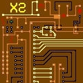
. well, I can make printed circuit boards, now.··and twenty minutes with my drawing program will be sufficient to "wire up" a test board.· If it called for hand-wiring, I wouldn't even consider experimenting...····· I can socket the 5 x 7·matrix blocks...
. AND ---> one column at a time·(per matrix, at least) may be the ONLY way I can do that - in order to have only just ONE lit LED per horizontal row - and so be able to supply the very same amount of current to each LED.· Forget (!) my patterns up above - I wouldn't be able to get consistantly even illumination.
. thank you one and all.