Shop OBEX P1 Docs P2 Docs Learn Events
acroname ? — Parallax Forums

acroname ?

mark8mark8 Posts: 15
edited 2007-07-25 12:52 in General Discussion
attachment.php?attachmentid=73958Acroname moto board and md03 h bridge. The above is the file that was given to me. The tech support from acroname is Im not doing the math look in console etc bye bye. Their forum is not responding no support. 
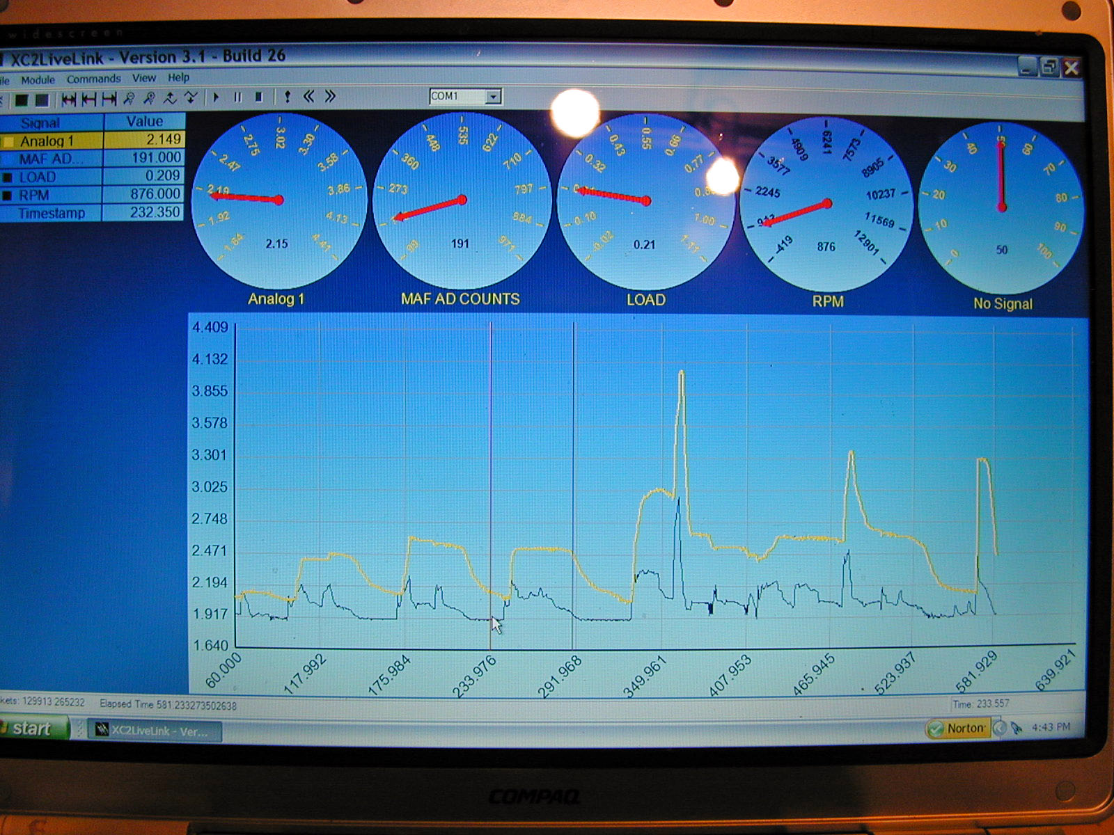
·Heres the problem. My motor-servo that has a ponentimeter feedback to the moto works flawlessly in every aspect except with the above file. I have attepmped 20 + stab in the dark configurations. Can I keep the md03 and then buy? a whatever parallax controller and then achieve my goals? My servo position hovers around 2 volts 0-5 when it should be· a· 1 volt input should equal a 1 volt position. The servo position is analog 1 yellow. ·Is the above program flawed?

Post Edited (mark8) : 1/28/2007 8:00:54 AM GMT
1600 x 1200 - 397K
339 x 742 - 15K

Comments

  • Desy2820Desy2820 Posts: 138
    edited 2007-01-28 10:34
    I'm not familiar with Acroname or this compilier, but at first brush, it looks like it's looking for a analog voltage on channel 4, then scaling the value and moving the servo.· Also, the program looks incomplete, I see the ADC input and scaling, but no output for the motor/servo and where is amotion_setpoint defined?· Is this the whole program?· It looks like this should feed another program or subroutine·PID loop, which would move the motor.

    How is the motor/servo/feedback wired?· My guess is, to make this work, the feedback potientometer needs one end tied to +5 volts and the other side to ground.· The center or wiper would go to channel 4.· Is this how it's wired?·

    Another thing to be careful with, are you using seperate supplies for the motor and the controller?· If yes, then you must tie all the·grounds together, but you must do this at only _one_ place, otherwise you create a ground loop and even more problems.

    To answer your question about control with Parallax products, we need to know what the servo/motor is.· Any of the following: wiring diagram, link to website, model numbers, voltage/current etc.· Without knowing what your trying to control, I'm not sure we can help.


    Post Edited (Desy2820) : 1/28/2007 10:40:23 AM GMT
  • Kevin WoodKevin Wood Posts: 1,266
    edited 2007-01-28 13:01
    Do you have a working program to compare it to?
  • mark8mark8 Posts: 15
    edited 2007-01-28 13:48
    Desy2820 said...

    I'm not familiar with Acroname or this compilier, but at first brush, it looks like it's looking for a analog voltage on channel 4, then scaling the value and moving the servo.· Also, the program looks incomplete, I see the ADC input and scaling, but no output for the motor/servo and where is amotion_setpoint defined?· Is this the whole program?· It looks like this should feed another program or subroutine·PID loop, which would move the motor...................................Analog Mode - 0v-5v md03
    In this mode the motor is controlled by a 0v to 5v analog signal on the SDA line and direction on SCL.
    0v is stop position
    5v is full power
    Pin SCL is the logic level (ttl) direction control. logic 0 for reverse direction and logic 1 for forward direction. Its the whole program.

    How is the motor/servo/feedback wired?· My guess is, to make this work, the feedback potientometer needs one end tied to +5 volts and the other side to ground.· The center or wiper would go to channel 4.· Is this how it's wired?· ................................................Yes.

    Another thing to be careful with, are you using seperate supplies for the motor and the controller?· If yes, then you must tie all the·grounds together, but you must do this at only _one_ place, otherwise you create a ground loop and even more problems.
    I am using 4·AA batteries for the logic. I need to add more power? The regulator starts to work at 6volts.· The motor is running on the 12 volts from the cars battery. Its either a ground loop or I need to add a 10n snubbing capacitor or a 1000 uf across the motor leads.

    To answer your question about control with Parallax products, we need to know what the servo/motor is.·The servo is a 5 pin 3 for the pot 2 for the motor· 12 volts to motor 5 volts to pot. ·Any of the following: wiring diagram, link to website, model numbers, voltage/current etc.· Without knowing what your trying to control, I'm not sure we can help.··..........................········· http://·www.acroname.com/brainstem/hardware/moto/moto1.html

    ·http://www.acroname.com/brainstem/hardware/moto/moto_a2d_pid.html·When in ad pid it works great. When I am running the tea file·it hovers at a position of 2 volts. ....................(I will try running it in the tea program ·and then ground the signal return from the servo pot and see if it goes to a zero position. ......................................................................It was at a 2 volt position I then grounded the signal and it went to 1.2 volts.


    Post Edited (mark8) : 1/28/2007 4:11:54 PM GMT
    1600 x 1200 - 315K
    645 x 162 - 3K
  • FranklinFranklin Posts: 4,747
    edited 2007-01-29 03:31
    could you inclued the source of the other .tea programs?

    ▔▔▔▔▔▔▔▔▔▔▔▔▔▔▔▔▔▔▔▔▔▔▔▔
    - Stephen
  • mark8mark8 Posts: 15
    edited 2007-01-29 03:41
    I did some wiring cleanup. Originally I had pos and neg to motor along with the 3·pot wires and a 12 volt square wave tach signal all in one plastic sheathfreaked.gif· I twisted the pos and neg to motor together. I twisted the pot pos and neg. I am using a shielded interconnect for the signal return wire I have the shielding to ground only on the board. I now need to reroute the tach wire away from all other wires. I may want to run the tach wire in a shielded interconnect? I bought·some caps I dont know what a snubbing capacitor is. 10uf electrolytic non polarized·
    0.0047uf ceramic disc----.·

    Capacitors will absorb the energy stored in the inductive windings of the motor however in doing so, the voltage across them can go far above the motor drive voltage (hence the need for 300V breakdown). Another approach, which may be used in parallel with capacitors involves zener diodes. Two head to head zener diodes connected across the motor leads will clip voltage spikes coming from the motor. If the motor is running at 12V, 18V Zeners should be used. A higher substantially higher voltage is used because: Zeners ease into their conduction, it does not happen suddenly at their spec voltage. Depending on the motor drive circuit, the drive voltage may go over nominal for short periods or, for instance when NiCads are fully charged and first connected. Lastly, typically, other power elements of the drive circuit can handle 6V over voltages for short times or there are measures in the circuit to deal with them. Remember the point here is to reduce EM noise and clipping motor spikes at +/- 6V over nominal drive voltages is usually sufficient.····· The highest volt zener diodes at rat shack 1nt4742a 12 volt.··I should be able to tell if·twisting and isolating made any difference by datalogging. I need to completely rewire everything.

    Post Edited (mark8) : 1/29/2007 3:55:42 AM GMT
  • mark8mark8 Posts: 15
    edited 2007-01-29 03:59
    Franklin said...
    could you inclued the source of the other .tea programs?

    Im not sure what you mean. I have blindly·taken the motion_min 100 and changed that to 0·· 50·· -180 -200 I have also taken motion_max and changed that value. Changing the max value has a more profound affect imho it is overriding the emi corruption? My guess at this point If I hvave emi corruption attempting to change the tea makes no difference. Earlier today I was running the program I grounded the signal wire and the position went to min max of the servos limits .80 volts. I think it hovers at 2 volts because of my rookie wiring 8 feet of inline corruption. When I was experimenting weeks ago no tach signal the signal grounded was slowly creeping so maybe there was emi affecting it. When I run in ad/pid I have found that a setting for the input offset of around -180 seems to move the servo close to .80 volts position.

    Post Edited (mark8) : 1/29/2007 4:27:50 AM GMT
  • FranklinFranklin Posts: 4,747
    edited 2007-01-29 04:41
    #include <aMotion.tea>
    #include <aA2D.tea>
    These two files

    ▔▔▔▔▔▔▔▔▔▔▔▔▔▔▔▔▔▔▔▔▔▔▔▔
    - Stephen
  • mark8mark8 Posts: 15
    edited 2007-01-29 06:09
    Franklin said...
    #include <aMotion.tea>
    #include <aA2D.tea>
    These two files

    The person at acroname sent me the program file. I just searched their website and I couldnt find #include <aMotion.tea> as a definition. I did find hundreds of forum posts. I am completely lost with all of this.· ( The following should be ignored.I bought a futaba 2pl magnum·rc controller 3·weeks ago. I can run the md03 in rc mode. I was hoping for a configuration of I have digital trim of my servo via 2pl.· motion_min set on 2pl digital trim adjustable.·2.5 volts should be center stop position. motion_max can also be trimmed digitally? If I can splice into the controllers steering pot that should be 2.5 volts center stop and if·I send my 0-5 volt signal into the 2pl on the steerring channel I will have overidden the entire complex dilema for me programming of the microcontroller.·) I first need to address the core issues isolating interference magnetic fields.· A 0-5 volt signal controls a servos position very simple?

    ▔▔▔▔▔▔▔▔▔▔▔▔▔▔▔▔▔▔▔▔▔▔▔▔
    Developmental dyslexia is a condition or learning disability which causes difficulty with reading and writing. Its standard definition is a difficulty in reading and writing in spite of normal or above-average intelligence and cognitive abilities.

    Post Edited (mark8) : 1/29/2007 7:20:43 AM GMT
  • Desy2820Desy2820 Posts: 138
    edited 2007-01-29 10:10
    Since your reply indicated that you are running two different batteries.·PLEASE ensure·that you run a wire between the two batteries negative terminals.· Sometimes forgeting·to do this will cause strange problems.·

    For motor EMI, try a small disc capacitor across the motor's terminals.· The cap should be rated about 50 volts.· I think a value of .01uF to start with, but do some research.· It's not the voltage spikes, it's the RF/EMI noise from the motor that's usually the problem.· The small value cap helps reduce the noise.

    Hopefully, others will be able to help you further.·

    Last question, are you feeding the tach input to the ADC?· Or just not using it right now?· Judging by the info you posted,·the ADC·isn't supposed to have·an input above 5V.·
  • Kevin WoodKevin Wood Posts: 1,266
    edited 2007-01-29 11:31
    If you are new to robotics, electronics and programming, you might want to take a step back and start with an easier project. The Boe-Bot kit would be a good start. It is very well documented and easy to follow. You will also find more people here familiar with that kit, as opposed to the Acroname products.

    That being said, here is the page on the Acroname website that you should look at:
    www.acroname.com/brainstem/TEA/tea1.html

    TEA is basically a subset of C. C isn't too difficult to learn, but it can be difficult for beginners. You should consider getting a good beginners book, such as Absolute Beginner's Guide to C by Greg Perry.

    You can also check out this tutorial: cslibrary.stanford.edu/101/.

    Once you have the basics down, you'll have a much easier time understanding the programs.
  • Bruce BatesBruce Bates Posts: 3,045
    edited 2007-01-29 12:02
    Gents -

    If I'm reading something into this discussion that isn't really there, I herewith apologize. If, however, the eventual goal is to have a PBASIC Stamp drive this Brainstem Module, there may wll be a problem awaiting you, which will be somewhat difficult to overcome. This is particularly true for a beginner.

    Whenever one tries to use a piece of hardware that was designed to be operated from a PC, one must make sure that the necessary (asynchonous serial) communications protocal (if used) doesn't require FULL DUPLEX communication. FULL DUPLEX is the ability to transmit and receive data at the same time. This requires the use of a hardware UART for data buffering, which the PBASIC Stamp platforms do not possess. Thus, the PBASIC Stamp is incapable of full duplex communications directly.

    If this was not part of the eventual plan, please ignore this message.

    Regards,

    Bruce Bates

    ▔▔▔▔▔▔▔▔▔▔▔▔▔▔▔▔▔▔▔▔▔▔▔▔
    <!--StartFragment -->
  • mark8mark8 Posts: 15
    edited 2007-01-29 22:23
    Desy2820 said...
    Since your reply indicated that you are running two different batteries.·PLEASE ensure·that you run a wire between the two batteries negative terminals.· Sometimes forgeting·to do this will cause strange problems.· The md03 passes the groung internally from the battery of the motor.

    For motor EMI, try a small disc capacitor across the motor's terminals.· The cap should be rated about 50 volts.· I think a value of .01uF to start with, but do some research.· It's not the voltage spikes, it's the RF/EMI noise from the motor that's usually the problem.· The small value cap helps reduce the noise. Thats my next step. Also reading I came across a site saying something like if the motor leads are longer than 2 inches they should be twisted. I have another foot to twist. And seperate.

    Hopefully, others will be able to help you further.·

    Last question, are you feeding the tach input to the ADC?· Or just not using it right now?· Judging by the info you posted,·the ADC·isn't supposed to have·an input above 5V.·The tach signal goes into a convetor turns it into 0-5 volts. I am going to take the servo off the car rewire everything and test it etc. thanks
    ▔▔▔▔▔▔▔▔▔▔▔▔▔▔▔▔▔▔▔▔▔▔▔▔
    Developmental dyslexia is a condition or learning disability which causes difficulty with reading and writing. Its standard definition is a difficulty in reading and writing in spite of normal or above-average intelligence and cognitive abilities.
  • FranklinFranklin Posts: 4,747
    edited 2007-01-30 02:19
    BrainStem modules can operate in slave mode by responding to an extensive set of BrainStem commands.· When a module receives a command, it performs a simple task, such as moving a servo or returning a sensor reading.· Slave commands can be sent to the module via the configuration programs, the BrainStem Console, or any other serial (RS-232 or IIC) device.· You can also generate commands internally through reflexes or TEA programs.

    ▔▔▔▔▔▔▔▔▔▔▔▔▔▔▔▔▔▔▔▔▔▔▔▔
    - Stephen
  • mark8mark8 Posts: 15
    edited 2007-02-02 06:18
    I took the servo off the car did some wiring cleanup. I then added the first line that fixed a lot of problems. I will be adding all the others 1 at a time.
    ··· aMotion_SetParameter(1, aMOTION_PARAM_P, 450);
    ··· aMotion_SetParameter(1, aMOTION_PARAM_LATENCY, 5);
    ··· aMotion_SetParameter(1, aMOTION_PARAM_COFFSET,· 1);
    If The analog input does not have a stable signal it will go near 2 volts on the servos position. Signal to ground it now goes to .50 volts before it was 1.0 position the lowest I could obtain. With 2 AA s 2.33 volts between the ground and analog input = 2.33 servo position. Exactly what I need. Hopefully it will function properly when it goes back on the car.


    ▔▔▔▔▔▔▔▔▔▔▔▔▔▔▔▔▔▔▔▔▔▔▔▔
    Developmental dyslexia is a condition or learning disability which causes difficulty with reading and writing. Its standard definition is a difficulty in reading and writing in spite of normal or above-average intelligence and cognitive abilities.

    Post Edited (mark8) : 2/2/2007 6:43:57 AM GMT
  • mark8mark8 Posts: 15
    edited 2007-07-25 12:52
    I made some progress.· Second pic, Analog 1 yellow· is runner - servo position. Analog 2 dark blue is rpm converted to 0-5 volts. First pic, on the dyno graph delta 100 is the servo - runners longest position.· And the opposite for delta 1000. Making adjustments to the code below so the runner will be at its delta 1000 @ 4500 rpm should not be too difficult.··The problem is I need to hold the servo via code·at delta 100 until·the reading from value = aA2D_ReadInt(4); exceeds ( x voltage @ desired rpm·)· and then trigger·the main·program to take over.· I have $ in my paypal account and I am willing to compensate someone for their time. My other option is to buy an rpm activated switch set it to ground the input, that will hold the runners in the low position. When the rpm switch reaches its·trigger point that will·allow the voltage input to operate the code below.


    /* filename: glen.tea */

    /* this line is a comment that is ignored by the compiler */
    // so is this line

    #include <aMotion.tea>
    #include <aA2D.tea>

    // some simple constants to make the code below easier
    // to read and modify
    #define MOTION_MIN 1
    #define MOTION_MAX 1100
    #define MOTION_CHANNEL 1

    /* this is the main program, it loops for ever */

    void main()
    {

    · // since the value 1 below is always considered true,
    · // the while loop will run continuously
    · while (1) {
    ··· int value;
    ···
    ··· // here, we read the analog value from port 4.
    ··· // this value will be from 0-1023 which cooresponds
    ··· // to 0-5V input
    ··· value = aA2D_ReadInt(4);

    ··· // here, we clamp the reading to never be below
    ··· // a certain minimum defined above
    ··· if (value < MOTION_MIN)
    ····· value = MOTION_MIN;
    ·
    ··· // similarily, we clamp the value to never exceed a
    ··· // certain value···
    ··· if (value > MOTION_MAX)
    ····· value = MOTION_MAX;
    ···· // now, we send this position value to the PID loop
    ··· // to adjust the position the PID will try to reach
    ··· aMotion_SetSetpoint(MOTION_CHANNEL, value);
    ··· aMotion_SetParameter(1, aMOTION_PARAM_P, 450);
    ··· aMotion_SetParameter(1, aMOTION_PARAM_LATENCY, 10);
    ··· aMotion_SetParameter(1, aMOTION_PARAM_COFFSET, -50);
    ·} // while

    } // main

    if (value· =·< 200 MOTION_MIN·· 1)·· these 2 lines are guesses
    ····· value =MOTION_MIN;

    [*]You can loop (jumping for those assembly junkies) through your code by using special loop keywords. [*]These include while, for, and do while. [*]The while loops until the expression specified is false. For example while (x < 4) will loop while x is less than 4. [*]The syntax for for is different. Here's an example: for (i = 0; i < n; i++, z++). This code will loop until i is equal to n. The first argument specifies initializing conditions, the second argument is like the while expression: continue the for loop until this expression no longer evaulates to true. The third argument allows for adjustment of loop control variables or other variables. These statements can be null, e.g. for (; i < n; i++) does not specify initializing code. [*]do while is like a "repeat-until" in Pascal. This is useful for loops that must be executed at least once. Some sample code would be: do { /* do stuff */ } while (statement);

    This compiled no errors ?


    /* filename: glen.tea */

    [*]/* this line is a comment that is ignored by the compiler */
    // so is this line

    [*]#include <aMotion.tea>
    #include <aA2D.tea>

    [*]// some simple constants to make the code below easier
    // to read and modify
    #define MOTION_MIN 50
    #define MOTION_MAX 1034
    #define MOTION_CHANNEL 1

    [*]/* this is the main program, it loops for ever */

    [*]void main()
    {
    · do {
    ··· /* do stuff */
    · } while ( value < 200);
    ·· value = MOTION_MIN;
    · // since the value 1 below is always considered true,
    · // the while loop will run continuously
    · while (1) {
    ··· int value;
    ···
    ··· // here, we read the analog value from port 4.
    ··· // this value will be from 0-1023 which cooresponds
    ··· // to 0-5V input
    ··· value = aA2D_ReadInt(4);

    [*]··· // here, we clamp the reading to never be below
    ··· // a certain minimum defined above
    ··· if (value < MOTION_MIN)
    ····· value = MOTION_MIN;
    ·
    ··· // similarily, we clamp the value to never exceed a
    ··· // certain value···
    ··· if (value > MOTION_MAX)
    ····· value = MOTION_MAX;
    ···· // now, we send this position value to the PID loop
    ··· // to adjust the position the PID will try to reach
    ··· aMotion_SetSetpoint(MOTION_CHANNEL, value);
    ··· aMotion_SetParameter(1, aMOTION_PARAM_P, 50);
    ··· aMotion_SetParameter(1, aMOTION_PARAM_LATENCY, 10);
    ··· aMotion_SetParameter(1, aMOTION_PARAM_COFFSET,· 100);
    ·} // while

    [*]} // main

    ▔▔▔▔▔▔▔▔▔▔▔▔▔▔▔▔▔▔▔▔▔▔▔▔
    Developmental dyslexia is a condition or learning disability which causes difficulty with reading and writing. Its standard definition is a difficulty in reading and writing in spite of normal or above-average intelligence and cognitive abilities.

    Post Edited (mark8) : 7/27/2007 8:35:31 PM GMT
    1600 x 1200 - 409K
    1600 x 1200 - 408K
Sign In or Register to comment.