Decimal clock
Background;
About 10 years ago when teaching Physics I wanted to make a decimal clock. Students are usually concerned with when class is over so a decimal clock would cause them to deal with a conversion to know what time it is. (Or just memorize the time on the clock when class is over)
Theory;
Basically there are 86400 seconds in a day. I decided to divide the day into 10000 units (8.64 seconds). The clock would be set up to read X.XXX or 5.000 would be noon, 0.000 would be midnight etc. The main unit would be a deciday.
The display;
I chose to use 7 segment leds as my display. I found information on the Max 7219 LED driver chip here at the Parallax site. It includes schematics and diagrams of the circuit as well as software. (http://www.parallax.com/detail.asp?product_id=603-00001)
I used this app mod to figure out my display. I only used 4 digits and did not use leading digit blanking, (you’ll see that in the code I included below). The app mod does a great job of showing the circuit and software.
The clock;
I used the CD4060 oscillator with a 25.6 KHz crystal as the basis for the timing. Information on a similar use of the chip can be found here at the Parallax site. I used the basic stamp 1 application notes found here (http://www.parallax.com/html_pages/downloads/basicstamps/documentation_basic_stamp.asp) You’ll find the info in section 20 “An Accurate Timebase”. The difference is that I used the 25.6KHz crystal (from digi-key part number SE3302-ND) and I connected pin 1 on the CD4060 to pin 0 on my basic stamp 2 other wise the circuit is the same. Pin 1 on the oscillator produces 6.25 Hz or .16 seconds for the period which divides into 8.64 seconds 54 times.
The software;
I need to thank Tracy Allen from this forum for the software that reads the input from the clock. I was really stuck. I have some explanation in the code below for download on how the software works. A great deal of information about the CD4060 as well as how the project developed is found by following the thread “Decimal clock so close” in the Basic Stamp section of the Parallax forum.
Parts;
Most of the parts I had or found at Digi-Key. The Max 7219 drives common cathode LEDS.
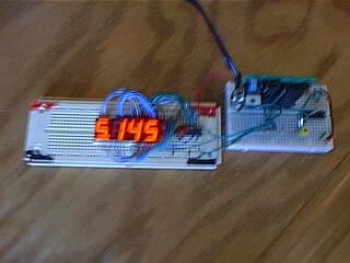
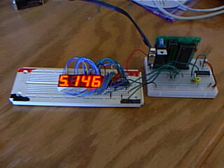
Pictures and software are found below.


Comments
I forgot to mention that I used a Basic Samp 2 OEM and that a nice improvement would be make the clock so the user could set it. Maybe 4 buttons and a LCD to interface to the user. (right now you have to set the clock in the code)
I would like to incorporate your invention into my class & introduce a no watch, cell, or clock policy
thanks
I planned to use the clock for basically the same reason, to force the students to convert from the base 24 clock to the base 10 clock. I will attach the information I used from Parallax to figure out the clock. The info includes the schematics. Be aware that the information is about slightly different projects so be sure and check the thread "Decimal clock so close" in the Basic Stamp forum. You can get parts from Digi-key or at Parallax. The parts from digi-key are; 1" 7 segement Leds part # 404-1127-ND, Maximum 7 Segment LED driver Part # MAX7219ENG+-ND, 25.6 KHz crystal part # SE3302-ND. You can find a great bread board at All Electronics part # PB-1680. All of the other parts I had but you can get them at Digi-key or at Parallax. (sorry I don't have the part numbers) I found that batteries did not last very long so a good power supply is needed. (Parallax has these) I used the Baisc Stamp 2 OEM kit from parallax as well. After you have sifted through all the info and have any questions, just let me know. What and where do you teach?
JCB
▔▔▔▔▔▔▔▔▔▔▔▔▔▔▔▔▔▔▔▔▔▔▔▔
Truly Understand the Fundamentals and the Path will be so much easier...
I agree we have a base 12 clock but for the conversion from the decimal clock to the base 12 and back requires the use of the military style 24 hour clock.
JCB
Thanks for the fun...
▔▔▔▔▔▔▔▔▔▔▔▔▔▔▔▔▔▔▔▔▔▔▔▔
Truly Understand the Fundamentals and the Path will be so much easier...
I guess it is all how you look at it
JCB
▔▔▔▔▔▔▔▔▔▔▔▔▔▔▔▔▔▔▔▔▔▔▔▔
Tracy Allen
www.emesystems.com