

Just learning i2c
 T Chap
Posts: 4,260
T Chap
Posts: 4,260
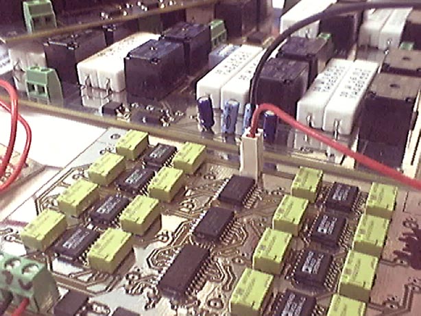
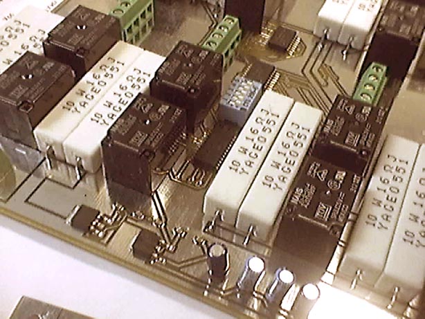
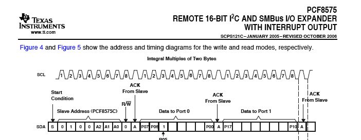
I made some relay boards that will be driven by the Propeller>PCF8575>ULN2803. The i2c part is a 16bit expansion i/o part. What I need to accomplish is very simple if you know i2c, but with no Spin examples on the exact or similar part, there are a few things to sort out still. There are a maximum or 8 boards that will be used, with 16 relays per board, I have shown a few boards below of the boards. In most cases there will only be one relay on per board at a time, so for example to turn on relay 1, here is what I think the entire Write should look like:
Start 'is start automatically part of the i2c object Write?
01000001 ' 0100 is device type 000 is addres 1 = write mode
ack
00000000
ack
00000001 'relay 1 is on
ack
Stop
For each relay board there is a dip switch to set the address. Would the best method to accomplish the example be the i2c object? If so, here is a snippet I found that seems like the rightidea, but I need to understand how to convert this to simulate the example above.
I appreciate any direction on what to do with this example or suggestions on where to look to learn this.
Start 'is start automatically part of the i2c object Write?
01000001 ' 0100 is device type 000 is addres 1 = write mode
ack
00000000
ack
00000001 'relay 1 is on
ack
Stop
For each relay board there is a dip switch to set the address. Would the best method to accomplish the example be the i2c object? If so, here is a snippet I found that seems like the rightidea, but I need to understand how to convert this to simulate the example above.
pub command1 : success                                             'sends first command
  success := i2c.writelocation (deviceaddress, $AC, $00, 8, 8)     'sends device's address, then the register, then the data.  8 address bits, 8 data bits
                                                                   'saves acknowledge bit from device to "success"
I appreciate any direction on what to do with this example or suggestions on where to look to learn this.
Comments
I think "1" is read, to "0" is write, regarding the last bit of your contol byte sent to slave...
Was that a typo?
-Parsko
CON _clkmode = xtal1 + pll16x _xinfreq = 5_000_000 i2cSDA = 26 i2cSCL = 25 LCD_Pin = 10 LCD_Baud = 9600 LCD_Lines = 20 Address = %0100_000_0 'address is 000 0 = write deviceRegister = 16 '???? VAR OBJ i2cObject : "i2cObject" PUB Start i2cObject.Init(i2cSDA, i2cSCL, false) i2cObject.Start repeat relayTest PUB RelayTest i2cobject.writeLocation(Address ??????) '0000_0000 0000_0001 relay 1 on waitcnt(80_000_000 + cnt) i2cobject.writeLocation(Address ??????) '0000_0000 0000_0000 relay 1 off waitcnt(80_000_000 + cnt)I'm gonna watch this post closely. I've been trying to get a 24FC515 eeprom to work via the same object and I2C for the last month, with no luck what-so-ever. I was actually going to start a thread myself (this week!) to try to figure out what is wrong, but I haven't completely ruled everything out (that I can find...) From what I can make it, you're going in the correct direction. I can explain the bytes you'll need for the "...writelocation" command:
deviceaddress - you're control byte
deviceregister - the address you want to write to in the slave
i2cdatavalue - the data value you want to write at the address (register)
addressbits - the number of bits in your address (register) (1 word = 16, 1 byte = 8)
databits - the number of bits in your data variable (1 byte = 8, 1 word = 16)
Anything past that, I'm a numbskull. Funny thing is, I'm scripting a 1Mhz I2C bitbanging protocol, and I can't even reliably write 1 byte to memory... grrrrrrr
Success!
-Parsko
I'm sorry that you have been having problems for the last month with the I2C object located in the object exchange.· I looked at the datasheet for the 24FC515, and it looks very similar to the datasheet for the 24LC256.· The main difference other than one being half the memory capacity of the other is that with the 24LC256 there are 3-lines for chip selection, while on the 24FC515 there are only 2.· The remaining bit is used to switch between memory banks to address the doubled memory size.· Here is an object that talks to the 24LC256... the main difference is in the "low level I2C routines".· The object exchange version in some cases will drive the SDA and SCL lines·HIGH even when you tell it not to.· The example below expects a pull-up resistor on BOTH the SCL and SDA lines and does not drive the lines HIGH.
▔▔▔▔▔▔▔▔▔▔▔▔▔▔▔▔▔▔▔▔▔▔▔▔
Beau Schwabe
IC Layout Engineer
Parallax, Inc.
Post Edited (Beau Schwabe (Parallax)) : 1/15/2007 5:51:05 PM GMT
The WriteWait routine is used to check for the end of a write cycle if you don't want to just wait a fixed period. It attempts to read from the device. Once the EEPROM begins a write cycle, it won't respond until it's done. You can use this to tell when the write is finished. The ReadPage and WritePage routines will handle more than one byte at a time. In the case of a read, you can read any size block from within one EEPROM device. In the case of a write, you are limited to within one page. For the 24FC512, this is a 64 byte page. Be careful! You may think you're writing to 64 successive bytes, but the address wraps around at the 64 byte boundary. If you write 64 bytes starting at location 32, you may think you're writing to locations 32-95, but you're actually writing to 32-63,0-31. The advantage to doing these block writes is that they're all written at once taking only one write cycle time (about 5ms).
Update: I added some constant definitions I had left out in cutting and pasting the routines for posting.
Post Edited (Mike Green) : 1/15/2007 7:55:45 PM GMT
If we use a 24LC512 instead of the 256 for Propeller EEPROM, can this driver be used to access the higher 256 for storage?
I've search the forums about using a 512, but haven't found anything.
Thanks,
Martin
Yes!
The 24LC256 that's been used with most of the Props so far (Demo Board, PropStick, PEkit) ignores bit 15 of the address that's presented to it. The 24LC512 works exactly the same, but uses bit 15 for addressing. The Protoboard will be using a 24LC512, so will have 64K x 8 EEPROM memory.
The driver I posted will work happily with a 24LC512. On a Hydra, with one or two Atmel 24LC1024 (128K x 8), it will happily handle a 256K x 8 address space. Beau's driver has an address mask in it of $7FFF. If you take that out, it will also handle a 24LC512 EEPROM. If you need more speed, the routines in the Propeller OS will handle up to a 512K x 8 address space using 8 - 64K x 8 devices. The OS_loaderInit.spin object is written to be usable by itself (without the rest of the OS) for general I2C I/O.
-Martin
Thanks much!
-Martin
So taking the example below again:
I may have the bytes written backwards to make relay 1 on, I am calling relay 1 : 00000000_00000001
but, trying to use your instructions:
deviceaddress - you're control byte
deviceregister - the address you want to write to in the slave
i2cdatavalue - the data value you want to write at the address (register)
addressbits - the number of bits in your address (register) (1 word = 16, 1 byte = 8)
databits - the number of bits in your data variable (1 byte = 8, 1 word = 16)
An EEPROM access consists of a device address byte followed by two address bytes that go into the address register (MSB first, LSB last) to specify where to begin the transfer, followed by one or more data bytes if you're writing. If you're reading, you have to reselect the EEPROM with a read transaction. The address register stays unchanged and is used for the address of the first data byte.
All this is described in Philips' documentation on I2C I/O and there are examples given in pretty much any datasheet for an EEPROM.
I left out a couple of constant definitions when I cut and pasted the I2C routines. Here they are:
The next attempt is with Mike's minimal object. It would be great to see an example of a code block using Mike's minimal routine. Would this be close?
i2cstart(clock_pin)
i2cWrite(i2cSCL, byte1) 'clock_pin followed by byte 1
i2cWrite(i2cSCL, byte2) 'clock_pin followed by byte 2
i2cStop(i2cSCL)
Is a wait for ack required after each write in this example above?
The goal is to send this:
01000000 'address
00000000 'port a data
00000001 'port b data
Post Edited (originator) : 1/15/2007 10:11:43 PM GMT
Thanks for the info. I used the AtomPro before, and it had canned I2C, so I never learned the protocol. I'm getting into it, and its basically like SPI. They all seem roughly the same at this point. My point, was that I now think I may have a hardware issue on the plug-in board I'm using. Breadboarded one of the spares, but too many distractions tonight (my point, it think it's me, not the objects, wanted to make sure before foot/mouth issues arise). Now it's time to take out the garbage and go to bed...
Originator, I think you missed a write in there. You are writing 3 bytes, from the diagram you have in your first post above. I think it's start, write control, write data0, write data1, stop. Also take care of your MSB/LSB issue.
-Parsko
I think your sequence for reading the registers would be
For writing
The next problem is, I can turn on any one of 16 outputs as you see in the code, but the pin never turns back off. This again could be a result of the PS.
At least the IC seems to be attempting to do it's job! You know how it is when months of work come together as planned.
* 1250mA supply is the same, .9V on every out.
**I removed both i2cstop lines, changed the pauses to any size length and the outputs now follow the data.
Post Edited (originator) : 1/16/2007 1:24:42 AM GMT
I am wondering if I swap the PCF8575 Vdd with 5V instead of 3.3V, maybe it will bump it up enough to turn on the darlinton and take the relay to GND. There is no current limiting resistor between the Prop and the PCF8575 in case the IC were to output 5 volts.
Post Edited (originator) : 1/16/2007 2:19:53 AM GMT
I tried a 6amp 12vdc supply, still only around .95 volts on the outs.
Post Edited (originator) : 1/16/2007 3:04:30 AM GMT
**10k or 20k does the job. Thanks for solving that for me Mike.
Post Edited (originator) : 1/16/2007 4:12:19 AM GMT
I have used numerous PCF8574 chips over the years for exactly the same purpose.
These are the 8 way type ..
These chips as Mike G. mentioned have Quasi outputs.
The pins can be either an input or an output ..(on the PCF8575 )
As an output they can only really sink about 25mA according to the spec sheet I have but they
can source no current at all as the output is an open drain type output.
You might be able to get enough drive to the input of the ULN2803 with a smallish pull up resistor
but be carefull not to exceed the max output current the PCF chip can drive.(max sink current of the PCF chip)
You would have to invert the signalling as well ( as off (output from PCF) means high to the ULN chip)
The ULN chips are neat as they have diodes built in for back emf surpression for when the relay turns off.
I have used also small opto looking like relay driver chips single bit type PC852 from SHARP
They work great but do need a diode for the back EMF surpression when driving inductive loads.
Cheers to all its is Damm Hot here today 41 Celsius ...
Ronald Nollet
Melbourne Australia
(16 i/o's * 8 ic's per i2c bus) * 8 cogs I meant to say
Post Edited (originator) : 1/17/2007 1:00:52 PM GMT
You can have as many I2C busses as you are willing to dedicate pairs of pins, each with 8 addressable expanders. The routines I posted require you to supply the pin number of the clock pin on each call. This is deliberate so that you can use more than one buss easily. If you want to change the routines to allow for separate specification of clock and data pins, you could even share all the data pins as long as each buss had its own clock pin. You'd have to be careful about buss loading with a lot more than 8 devices on a pair of pins. Note that you can mix different kinds of devices on the same buss (8 I/O expanders plus 8 EEPROMs).
Mike