

Power supply
 computer guy
Posts: 1,113
computer guy
Posts: 1,113
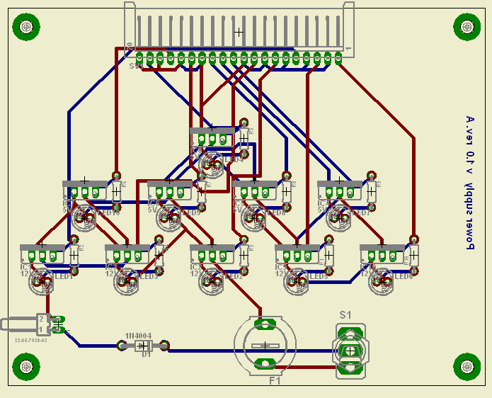
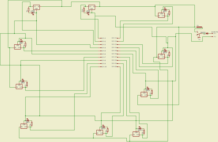
I am looking at making a power supply for my robot with 24v in to it and 5x 5V out and 5x 12V out.
Is this ok or do you think it needs changes.
(Pictures attached)
Post Edited (computer guy) : 1/15/2007 6:32:34 AM GMT
Is this ok or do you think it needs changes.
(Pictures attached)
Post Edited (computer guy) : 1/15/2007 6:32:34 AM GMT
Comments
Jeff T.
Will save on parts that's for sure.
Thanks
Jeff T.
The leds on the psu where there to isolate a problem.
Thanks
Jeff T.
Jeff T.
Realy easy to use.
Thanks for your help.
What fuses would i use (look at schematic above) with these batteries -
www.jaycar.com.au/productView.asp?ID=SB2482
and these regulators -
www.jaycar.com.au/productView.asp?ID=ZV1505
and
www.jaycar.com.au/productView.asp?ID=ZV1512
One last question
What diode would i use all i want it to do is protect from reverse polarity.
Thank you
P.S I love electronics but only learn little bits on occasion so please if my questions are stupid it's my fault.
Post Edited (computer guy) : 1/15/2007 5:16:20 AM GMT
Here is what you are looking for this is an adj reglator 1.5 to 37 volt @ 5 amp case steel can T-03
·http://www.digikey.com/scripts/dksearch/dksus.dll?Detail?Ref=5399&Row=536647&Site=US
Here is a 5 volt reglator @ 3 amps· T-03 can
http://www.digikey.com/scripts/dksearch/dksus.dll?Detail?Ref=2236&Row=202312&Site=US
▔▔▔▔▔▔▔▔▔▔▔▔▔▔▔▔▔▔▔▔▔▔▔▔
··Thanks for any·
·
·
·
·
Sam
Post Edited (sam_sam_sam) : 1/15/2007 6:24:51 AM GMT
Jeff T.
·
▔▔▔▔▔▔▔▔▔▔▔▔▔▔▔▔▔▔▔▔▔▔▔▔
··Thanks for any·
·
·
·
·
Sam
Post Edited (sam_sam_sam) : 1/15/2007 6:36:53 AM GMT
I live in Australia and don't like paying postage if i don't have to.
I just gave you those link for Data Sheets and Parts No
If you use these REG make sure that you use a HEAT SINK with them or they will over HEAT
If you have a load of more than 200 milamps on them then you will need a heat sink on them
▔▔▔▔▔▔▔▔▔▔▔▔▔▔▔▔▔▔▔▔▔▔▔▔
··Thanks for any·
·
·
·
·
Sam
Post Edited (sam_sam_sam) : 1/15/2007 7:02:42 AM GMT
Those links you gave me are to adjustable regulators not fixed and i don't have experience with adjustable regulators.
So i will need to talk to them and see if they have a fixed regulator.
Thanks still need the answers to my questions i asked in a previous reply.
1. Should i be using 2 12v batteries in series or parallel to go to the psu?
2. What fuses would i use (look at schematic above) with these batteries -
www.jaycar.com.au/productView.asp?ID=SB2482
and these regulators -
www.jaycar.com.au/productView.asp?ID=ZV1505
and
www.jaycar.com.au/productView.asp?ID=ZV1512
3. What diode would i use all i want it to do is protect from reverse polarity.
Thank you
Answering the question on connecting the two 12V batteries, in series will give you a 24V battery in parallel will give you a 12V battery.
The protection diode should be rated to withstand the maximum reverse voltage which would be the value of the battery supply and be able to carry·the maximum expected forward current which is the current on the 5V plus the current on the 12V lines, check the data sheets.
Before you buy your parts you need to calculate the total current for each power rail, whether they need to be regulated or not and decide what configuration of battery will do the job best.
Jeff T.
I need to regulate the 12 Volt lines for my motors cause my motor controllers need a regulated 12 Volt source.
Would one 12 Volt battery be enough to power the PSU? Or do i need 2 in series (24V).
Here is the data sheet.
www.jaycar.com.au/products_uploaded/LM7512C.pdf
Post Edited (computer guy) : 1/15/2007 11:17:04 PM GMT
One thing that hasn't come up here is that if we're really talking in terms of several amps, the pcb trace widths will have to be seriously widened.
As was mentioned, the motor regulators are going to be smoking hot ( say dropping 12volts at 5 amps = 60 watts !!) This is really a good case where the motors should be run off a battery voltage close to what they need.
Cheers,
▔▔▔▔▔▔▔▔▔▔▔▔▔▔▔▔▔▔▔▔▔▔▔▔
Tom Sisk
http://www.siskconsult.com
·
I think i have worked out another idea will post soon.
Thabk you
What is the total (max) current you need for each rail (5V and 12V)? Is there always a minimum current draw on the 5V rail? Where Im going with these questions is using a computer switching supply may be your easiest route (assuming your application will be near an outlet).
Im not comfortable with a couple elements of your design, first using 2 12V batteries does not fit well with you intended application. Wiring them in parallel will yeild 12V which isn't enough for the 12V regulators, wiring them in series will produce 24V which is _alot_ of voltage to be feeding to the 5V regulators, 19V will be bled off in the form of heat and is highly inefficient.
Second it is always best to minimize your part count, it would be much better to use a 5A regulator than 5-1A regulators. I know your in OZ and it's not easy to find parts. Some regulators permit connecting them in parallel, but I saw no mention of this in the spec sheet so I wouldn't try it.
Are you having the board fabbed or making it yourself? If you are having it fabbed, the decrease in fab cost may offset getting a couple 5A regulators shipped from the states.
Ultimatley your board will probably work as you expect it to, it's not the most efficient (ie read more battery charges required) but that may not be a high priority for you.
▔▔▔▔▔▔▔▔▔▔▔▔▔▔▔▔▔▔▔▔▔▔▔▔
Paul Baker
Propeller Applications Engineer
Parallax, Inc.
Post Edited (Paul Baker (Parallax)) : 1/16/2007 11:15:18 PM GMT
I have decided to have 2 regulated 12v batteries (already regulated) one will go to my motor controllers and the other to a 5 volt switching regulator circuit i am getting from the states. The second one will power my sensors and thing.
P.S can you run the BOE from 5 volts regulated or do i have to put another battery in this thing?
Thank you all
If your Stamp isn't switching a bunch of LEDs or similar loads (just logic loads), you could run it off the 12V. The main reason for limiting the maximum Vin is the power dissipation in the Stamp's internal regulator (with a 7V drop to +5V times the current drain of the Stamp and it's I/O). You could also just put a couple of series diodes between the 12V supply and the Vin of the BOE. Each would drop 0.7V and take some of the power dissipation. 4 to 5 diodes in series (like 1N4001) would do the work nicely and are pretty cheap and readily available.
www.parallax.com/html_pages/products/componentshop/power.asp
Is that true? can the BOE be powered from 12V dc?
Thanks
Post Edited (computer guy) : 1/19/2007 6:47:56 AM GMT