Simple Oscilloscope
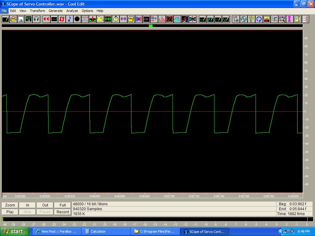
Here's a cheap and easy way to check and measure wave forms coming from your·Basic Stamp projects.
See Post below for realtime software. You can time your code's instructions and loops by setting a pin high then low and measuring it in cool edit with the selection tool.
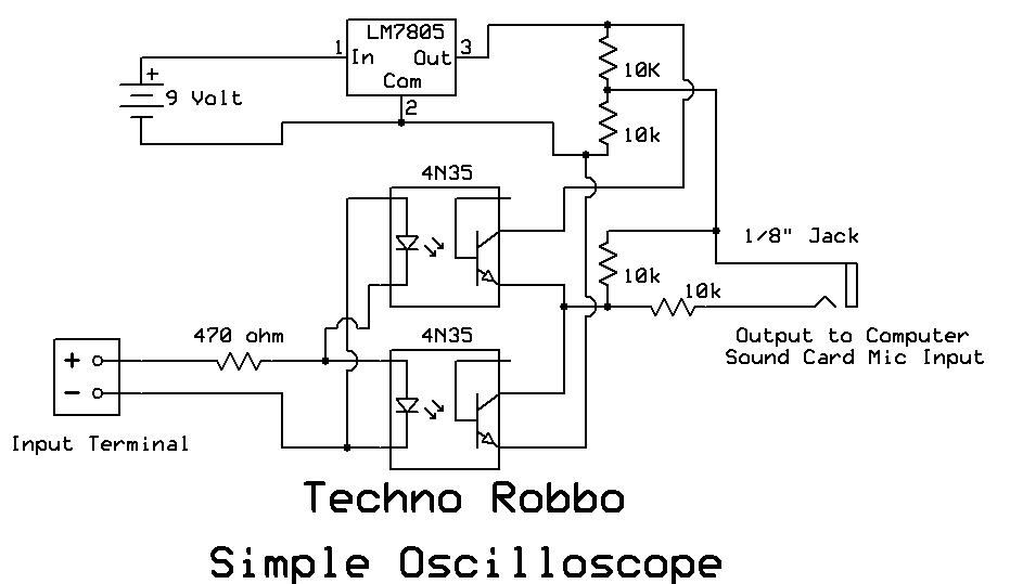
It's primarily designed to work with 5V but you can use resistors to divide higher voltages. The Optocouple protects your computer.
All sorts of possibilities.
Parts:
· A Computer with sound card
· 1/8" mono audio cable
· a 4N35 Optocoupler
··miscellaneous parts from Radio Shack
· a copy of Cool Edit 96 or similar (See post below realtime Oscilloscope software)
Assemble the diagram below - connect the output of the adapter to the mic input of the sound card.
Set the recording properties in windows for the mic and adjust the levels.·
See Post below for realtime Oscilloscope software(shareware)
Cool Edit Instructions:
Cool Edit has a level meter to help you with this.
Set the timeline in cooledit to Custom - 1000/frames per second
Attach wires from your project to the terminal - polarity's important.
Start recording at 48,000 Hz 16 Bit Mono and you'll have a resolution down to 0.0000208 of a second.
·
▔▔▔▔▔▔▔▔▔▔▔▔▔▔▔▔▔▔▔▔▔▔▔▔
Have Fun
TR
Post Edited (TechnoRobbo) : 1/21/2007 5:59:54 AM GMT


Comments
http://www.zeitnitz.de/Christian/Scope/Scope_en.html
▔▔▔▔▔▔▔▔▔▔▔▔▔▔▔▔▔▔▔▔▔▔▔▔
Have Fun
TR
Post Edited (TechnoRobbo) : 1/14/2007 7:31:31 PM GMT
▔▔▔▔▔▔▔▔▔▔▔▔▔▔▔▔▔▔▔▔▔▔▔▔
Have Fun
TR
This question comes up often. Its nice to see all the necessary information on one page.
▔▔▔▔▔▔▔▔▔▔▔▔▔▔▔▔▔▔▔▔▔▔▔▔
- - - PLJack - - -
Perfection in design is not achieved when there is nothing left to add.
It is achieved when there is nothing left to take away.
http://www.zeitnitz.de/Christian/Scope/Scope_en.html·is AMAZING!!!! Very easy to use and very good!
I have been worried about using my·laptop as I did not want to blow my sound card... Your schematic (especially the revised one) is the perfect solution to protect my computer!
Very much appreciated post!!!!!!!!
Post Edited (Whelzorn) : 2/3/2007 4:49:16 AM GMT
Simply put - no. it captures sine waves just fine.·It's an analog circuit not a logic circuit
Steve Joblin,
I'm using the scope to read outputs from analog circuits. Yes, I too have connected direct without the circuit, but I don't while I'm prototyping. My worst fear is dead shorting my laptop while working on my prototype board(which I have done and hung it up and probably experienced data loss).
·
▔▔▔▔▔▔▔▔▔▔▔▔▔▔▔▔▔▔▔▔▔▔▔▔
Have Fun
TR
Post Edited (TechnoRobbo) : 2/4/2007 12:29:07 AM GMT
Are you planing on adding a second input.
After looking at SoundCardScope I noticed it has 2 inputs, left and right.
It would be cool to utilize this and add an extra input to your Oscilloscope.
▔▔▔▔▔▔▔▔▔▔▔▔▔▔▔▔▔▔▔▔▔▔▔▔
Check out my robot using the propeller robot.tmcp.com.au
If you offer cheap PCB fabrication, perl programming or any other helpful services please email me at.
anthonybmyatt@yahoo.com.au
▔▔▔▔▔▔▔▔▔▔▔▔▔▔▔▔▔▔▔▔▔▔▔▔
Have Fun
TR
Inherently being a klutz, I have avoided using the sound card for a scope because of the lack of isolation.
While the range may be limited to 20Khz-30Khz, it is great place to get started at a low budget.
▔▔▔▔▔▔▔▔▔▔▔▔▔▔▔▔▔▔▔▔▔▔▔▔
"Everything in the world is purchased by labour; and our passions are the only causes of labor." -- David·Hume (1711-76)········
▔▔▔▔▔▔▔▔▔▔▔▔▔▔▔▔▔▔▔▔▔▔▔▔
*.*
Ibsen
" It's nice to be important, but
·· more important to be nice... "
▔▔▔▔▔▔▔▔▔▔▔▔▔▔▔▔▔▔▔▔▔▔▔▔
Have Fun
TR
Since I had all the parts at home, it took about 3 hours for me to build a 2 channel version of the opto-isolation that plugs into audio line in.
Initially, I am going to try to use it to monitor my TV's IR remote control output. After that, I hope to use a BasicStamp or SX as a decoder and have the unused feature buttons on the remote used to control lighting or other devices via SSRs.
I suppose you could have the USB power output provide the 5volts, but it seems to me that the additional cord with plug would just be another hassle and cost more than using a 9volt battery. Using the 9volt battery eliminates the possible entry of noise via the power supply and batteries are inherently quiet.
And, the regulation is important for a stable reading. I used a tiny 100ma regulator, a 78L05.
▔▔▔▔▔▔▔▔▔▔▔▔▔▔▔▔▔▔▔▔▔▔▔▔
"Everything in the world is purchased by labour; and our passions are the only causes of labor." -- David·Hume (1711-76)········
Any chance you can post a schematic of your 2 channel isolator?
▔▔▔▔▔▔▔▔▔▔▔▔▔▔▔▔▔▔▔▔▔▔▔▔
Have Fun
TR
I haven't drawn anything - just visualized a parallel set of 4n35s.
In other words, I used the single channel schematics with one 7805 as shown, but doubled up on the 4n35 chips.
The input side is quite easy due to the isolation, just a duplicate.
The output side requires a little more thought as you have to be sure to connect to the 7805 voltage divider at the right locations. Still you have only one output that is ground. Each pair of 4n35s have to have the right 'high side' and the right 'low side' orientation. And you have to add an extra set of 10K resistors.
TechnoRobbo,
I have never bought a laptop and until very recently I didn't have any real experience with them. But when i recently visited a friend, the heat during operation was quite noticeable and I really didn't like it. If I ever get a laptop, I certainly won't depend on the USB port for auxilary power beyond conventional USB interfacing. Hopefully, I won't have to depend on PCMCIA to get USB2.0
▔▔▔▔▔▔▔▔▔▔▔▔▔▔▔▔▔▔▔▔▔▔▔▔
"Everything in the world is purchased by labour; and our passions are the only causes of labor." -- David·Hume (1711-76)········
I would like to know what i must get if i measure 5v.
I·get a funny looking sinewave with a lot of spikes all over.
Could it be that i used·pc817 optocoupler in stead of the 4n35 opto!
before i made the circuit a tested the software and i notice when i touch the input that i get a sqaure wave.
With the circuit i get nothing when i touch the input.
I am still a bit of a noob please help.
greetings
Vick
▔▔▔▔▔▔▔▔▔▔▔▔▔▔▔▔▔▔▔▔▔▔▔▔
Have Fun
TR
Post Edited (TechnoRobbo) : 8/29/2007 10:31:15 AM GMT
What about a capasitor if i slip.It will block the AC wont it?
▔▔▔▔▔▔▔▔▔▔▔▔▔▔▔▔▔▔▔▔▔▔▔▔
Quit buying all those fixed voltage regulators, and·get an Adjustable Power Supply·for your projects!· Includes an LED testing terminal!
(no longer new) SD Card Adapter·Now available!· Add extra memory to your next Propeller project with ease!