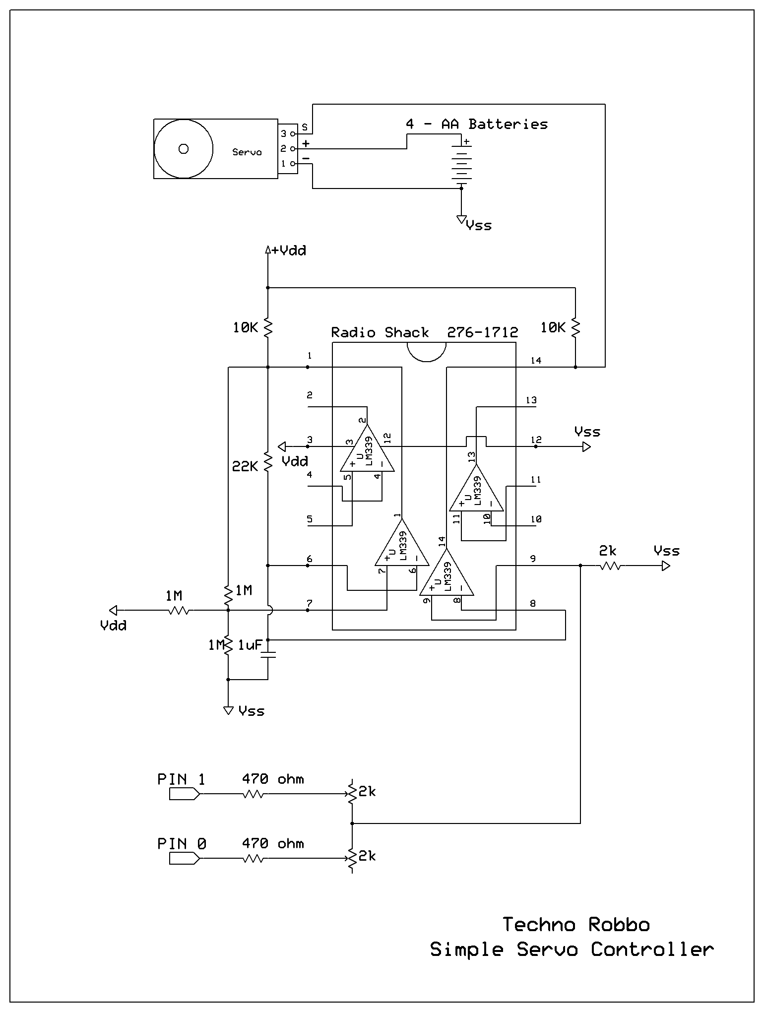
Simple Continous Servo Controller
This circuit is intended to roll a continuous servo with out chewing up Basic Stamp processing time. The LM339 comparator can be wired up for maximum of 2 servos so you can run your BOE Bots without using time consuming Pulsout commands.
You can also use this circuit with a standard servo if you only want preset positions. Any number of IO pins can be wired for preset for 1 controller circuit.
The circuit has 2 trimpots (potentiomenters) that you adjust for the servo position, speed or direction.
Set the IO pins to "INPUT" to shut off the motor. Set the pins to HIGH to activate preset position.
An example program is included below with the schematics.
·
▔▔▔▔▔▔▔▔▔▔▔▔▔▔▔▔▔▔▔▔▔▔▔▔
Have Fun
TR
Post Edited (TechnoRobbo) : 1/14/2007 1:51:18 AM GMT


Comments
Can you explane how this routine works
I thought that when you use a HIGH command to turn pin ON that you had
to use a LOW command to turn OFF that pin
I am still learning how to use a Basic Stamp I have not seen this one before
This might a stupit question help me understand how this work
Many Thanks for your help and time in this matter
INPUT 1 'cutoff pin's driver
HIGH 0
PAUSE 5000
' {$STAMP BS2}
' {$PBASIC 2.5}
INPUT 0 'cutoff pin's driver
INPUT 1 'cutoff pin's driver
Main:
DO
INPUT 1 'cutoff pin's driver
HIGH 0
PAUSE 5000
INPUT 0
HIGH 1 'cutoff pin's driver
PAUSE 5000
LOOP ' do it again
END
▔▔▔▔▔▔▔▔▔▔▔▔▔▔▔▔▔▔▔▔▔▔▔▔
··Thanks for any·
·
·
·
·
Sam
Most circuits you use will require you to set the output pin to low but in this case it doesn't.
Hope my explanation was clear. I know we tend to treat binary logic as ones and zeros but in real world there really is no such thing.
▔▔▔▔▔▔▔▔▔▔▔▔▔▔▔▔▔▔▔▔▔▔▔▔
Have Fun
TR
Thanks for your reply
I search on the web for tri-state aka high impedance or hi-z mode
and found something to read on this subject and i have a better understanding of what is
going with what you have here
Thanks again for explane this to me
▔▔▔▔▔▔▔▔▔▔▔▔▔▔▔▔▔▔▔▔▔▔▔▔
··Thanks for any·
·
·
·
·
Sam
▔▔▔▔▔▔▔▔▔▔▔▔▔▔▔▔▔▔▔▔▔▔▔▔
Have Fun
TR
▔▔▔▔▔▔▔▔▔▔▔▔▔▔▔▔▔▔▔▔▔▔▔▔
Have Fun
TR
I knew that was what that mean AKA stands for·"also known as
One thing i look at your schematic I did not see any changes yet
I uploaded a new schematic changing the 2 resistors to 470 ohm - this makes calibration much easier.
Thanks for all of your help
▔▔▔▔▔▔▔▔▔▔▔▔▔▔▔▔▔▔▔▔▔▔▔▔
··Thanks for any·
·
·
·
·
Sam
▔▔▔▔▔▔▔▔▔▔▔▔▔▔▔▔▔▔▔▔▔▔▔▔
Have Fun
TR
I· see it now
Thanks
▔▔▔▔▔▔▔▔▔▔▔▔▔▔▔▔▔▔▔▔▔▔▔▔
··Thanks for any·
·
·
·
·
Sam
You can use the BS2 circuit above to control it.
A D/A or a digital potentiometer and some trimpots to control the high and low voltage.
Use an R-2R resistor ladder.
You can also run it by hand with a potentiometer and a 9 volt battery
▔▔▔▔▔▔▔▔▔▔▔▔▔▔▔▔▔▔▔▔▔▔▔▔
Have Fun
TR
Post Edited (TechnoRobbo) : 1/27/2007 5:03:31 AM GMT
' {$STAMP BS2}
' {$PBASIC 2.5}
x·· VAR···· Byte
LOW 2
LOW 3
x=64
DO
· DO WHILE x < 128
··· PULSOUT 3,1
··· PAUSE 10
··· x=x+1
· LOOP
· TOGGLE 2
· PAUSE 1000
· DO WHILE x >0
··· PULSOUT 3,1
··· PAUSE 10
··· x=x-1
· LOOP
· TOGGLE 2
· PAUSE 5000
LOOP
END
▔▔▔▔▔▔▔▔▔▔▔▔▔▔▔▔▔▔▔▔▔▔▔▔
Have Fun
TR
▔▔▔▔▔▔▔▔▔▔▔▔▔▔▔▔▔▔▔▔▔▔▔▔
Have Fun
TR