

Any tube amp experts?
 T Chap
Posts: 4,260
T Chap
Posts: 4,260
I am building a routing system to route a guitar to any of 16 guitar amp inputs via relays. There are 3 relay boards, one to choose the amp to send the guitar to, one to choose which amp to send back out to a cab, one to choose the speaker cab to listen to. All the amps belonging to the clients of the gadget are exotic pricey tube types, ones that I do not want to blow up. If no load is on some amps, and you hit it, the amp dies. I have also sorts of opinions on how to do this, but am still not settled on it yet. Maybe someone here who knows more about tube amp fundamentals can help me out.
The guitar distribution is pretty straightforward. I don't want anything in the path except relays. The only exception is an option to drop in a transformer to convert the signal to balanced, since there is loss, I may bump this back up with an op amp with a +-5v supply attached, lower power for lower noise, since it is a small signal. A transformer box will sit on each amp for balanced to unbal conversion. A Propeller receives a serial input from a computer, and selects the correct amp(via relay) from a menu list. The timing will allow all inputs to see GND prior to switching the amp outputs. Once the amp input relay is selected, plus the amp output relay, the input(guitar) is then patched in. This way, no amp sees input until it is loaded with a speaker. What I need to resolve is, whether to keep some amount of load on all unused amp outputs. I was thinking about something higher than 4, 8 or 16, maybe around 100 - 200 ohms, using lower wattage, since at this resistance(impedance) there will be less heat. I'd like to use a 3 watter since I can get them in a convenient SMT package. With no signal, is this safe thinking to use such a low wattage resistor? I have heard that with no signal that no load is really necessary. But to be safe I am looking for more advice.
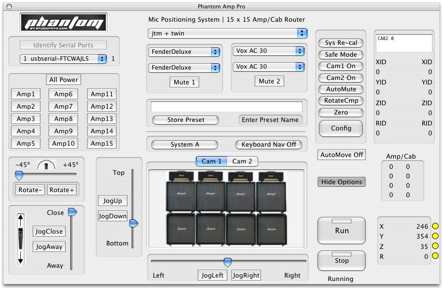
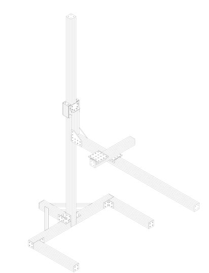
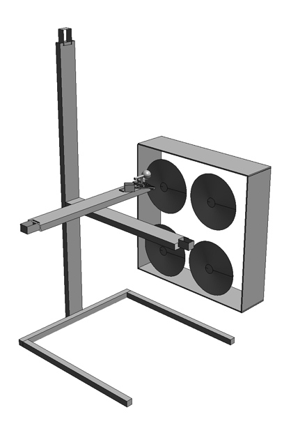
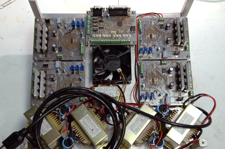
BTW for the guitar folks, this system is also a remote controlled mic stand. It moves a boom around a row/stack of amps and positions the mic anywhere on a speaker(several cameras are displayed in the app--wide angle and closeup looking down on the mic). The position is stored in a namable preset in the app for future recall. The amp and cabinet are stored in the preset as well, so on selecting the name from the preset menu, the mic goes to it's precise place, and the correct amp and cab are patched in. Future versions will have an effects loop router for all pedals, outboard gear. Below is a screen shot of the beta app, it contains a bit of diagnostic stuff on the right that will be hidden from the user later. The Propeller is used on all relay switching boards, and is connected serially(rs232 or XBee) to the computer, it controls the 4 steppers including all motion control code, accel, decel, etc. The full blown proto with vid coming soon, the extruded aluminum framing will arrive any day. The boom moves up down(6' typ), left right (4' typ), in out( 2') and rotates the mic +- 45). All navigation is via mouse or keyboard arrows. Future versions will include USB joystick control. The router actually controls sets A and B, so two amps can be used, and two cabs can be controlled at once. Shown is the Propeller 4 motor controller board, plus 4 separate drivers, 5 supplies.
Post Edited (originator) : 1/4/2007 6:34:15 AM GMT
The guitar distribution is pretty straightforward. I don't want anything in the path except relays. The only exception is an option to drop in a transformer to convert the signal to balanced, since there is loss, I may bump this back up with an op amp with a +-5v supply attached, lower power for lower noise, since it is a small signal. A transformer box will sit on each amp for balanced to unbal conversion. A Propeller receives a serial input from a computer, and selects the correct amp(via relay) from a menu list. The timing will allow all inputs to see GND prior to switching the amp outputs. Once the amp input relay is selected, plus the amp output relay, the input(guitar) is then patched in. This way, no amp sees input until it is loaded with a speaker. What I need to resolve is, whether to keep some amount of load on all unused amp outputs. I was thinking about something higher than 4, 8 or 16, maybe around 100 - 200 ohms, using lower wattage, since at this resistance(impedance) there will be less heat. I'd like to use a 3 watter since I can get them in a convenient SMT package. With no signal, is this safe thinking to use such a low wattage resistor? I have heard that with no signal that no load is really necessary. But to be safe I am looking for more advice.
BTW for the guitar folks, this system is also a remote controlled mic stand. It moves a boom around a row/stack of amps and positions the mic anywhere on a speaker(several cameras are displayed in the app--wide angle and closeup looking down on the mic). The position is stored in a namable preset in the app for future recall. The amp and cabinet are stored in the preset as well, so on selecting the name from the preset menu, the mic goes to it's precise place, and the correct amp and cab are patched in. Future versions will have an effects loop router for all pedals, outboard gear. Below is a screen shot of the beta app, it contains a bit of diagnostic stuff on the right that will be hidden from the user later. The Propeller is used on all relay switching boards, and is connected serially(rs232 or XBee) to the computer, it controls the 4 steppers including all motion control code, accel, decel, etc. The full blown proto with vid coming soon, the extruded aluminum framing will arrive any day. The boom moves up down(6' typ), left right (4' typ), in out( 2') and rotates the mic +- 45). All navigation is via mouse or keyboard arrows. Future versions will include USB joystick control. The router actually controls sets A and B, so two amps can be used, and two cabs can be controlled at once. Shown is the Propeller 4 motor controller board, plus 4 separate drivers, 5 supplies.
Post Edited (originator) : 1/4/2007 6:34:15 AM GMT
894 x 583 - 107K
412 x 538 - 10K
418 x 611 - 39K
722 x 480 - 124K
Comments
kelvin
My amps have standby switches on the back. I don't know if you are willing to mod their amps at all, but I'd try switching to standby before switching in puts.
The standby, I THINK, retaps the grid voltage on the tubes. The tubes will still be lit but will not have full power until you go off standby.
If you are not able to mod their amps (I personally wouldn't want it mod'd), you'd have to look at "make-before-break" setups to switch in an RC load of some sort.
I'd normally just go with a resistor, but there will still be a whoomp of some sort (as g'tar guys like to have their amps turned up)....the capacitor would hopefully buffer the load as things change.
If you implemented audio transformers in your outputs of your "switching" box, then you might be able to get away with the output impedance of your box being enough of a load on the amp and then do your switching before the audio transformer. Essentially the transformer would offer some isolation....not sure how much though.
And to note, mechanical relays are very noisy accoustically....all that arc'ing when you switch just gets amplified through amps/pedals and all...
Interested to see your progress though.
▔▔▔▔▔▔▔▔▔▔▔▔▔▔▔▔▔▔▔▔▔▔▔▔
·
Steve
"Inside each and every one of us is our one, true authentic swing. Something we was born with. Something that's ours and ours alone. Something that can't be learned... something that's got to be remembered."
if the signal is not there, the amp is not powered up, or switched in??????
There are also circuits that sense an output load for amp protection ( I believe solid state )....
Bob
What you have to do is keep the output of your switch from creating any unwanted noises when switching. The relay will create an arc regardless of what's at your input. This arc will go through your output and into the amps where it will give a nasty whoomp.
Even if you disabled the output of your switch, the amp would more than likely make a noise (not sure what...but essentially it lost it's load and it's input will float).
As far as detecting what's been plugged in.....I'll assume the speakers have mono 1/4" jacks on them.
You can use a stereo jack and look for signal between the Left and Right rings on the plug...or even from Left/Right to ground...not sure.
On your switch end, you can have a jack that is switched...so that whenever you plug something in, it'll close the contacts and complete teh circuit (not sure if I described that right).
Even with the plug in your output, you could still look to see if there's continuity between the Left/Right plugs so you will know you're connected.
NOW, the trick is....you can't use a standard DMM continuity circuit since it uses DC...last thing you want to do is put DC on your speaker. We used to test our speaker coils with a 9volt battery...would pin the coil in one direction.
You'll maybe want to use a signal below/above the range of hearing.....
I like the project....but don't really know the best road to take!
▔▔▔▔▔▔▔▔▔▔▔▔▔▔▔▔▔▔▔▔▔▔▔▔
·
Steve
"Inside each and every one of us is our one, true authentic swing. Something we was born with. Something that's ours and ours alone. Something that can't be learned... something that's got to be remembered."
The arcing is part of the deal, not much way around it. The other possibility I had in was mind was to have a mic mute feature that mutes the mics before all switching, then unmutes afterwards. Another thought in mind is to use a digital pot or switch, and ramp the amp input to GND prior to switching the relays, thus the amp is seeing GND before the relay changes states, This would however leave a circuit connected to all amp inputs even when in high impedance states, but that artifact may not be of consequence. I am looking at digital pots and swithes right now to decide. Ramping a voltage up and down with a DA to a coltage controlled pot is more ideal, with smoother transitions since there is no need in switching on the fly, dead time can be even a second as the mic has to move to a new place anyway, who cares if there is no instantaneous switching. Since it is Propeller controller, ramping a voltage is very easy, as well as sending one serial signal to all 16 digital pots(or vcs's) to mute them in every state change.
Post Edited (originator) : 1/5/2007 9:58:23 PM GMT
But you could in a Gate Source Drain type of setup, you would enable the JFET with a voltage at the Gate. now, this would be a DC signal to enable it, which means you're signal would ride on the DC and you'd have to decouple it before it goes out to the amps...no biggy..DC blocking cap is all (cap in series with output).
What would be nice is to have the amp see the same impedance at all times at it's input so that there is no noise introduced. How do you do this?? haha not sure.
A transformer with a resistor in parallel?? Don't know if it's that simple....
▔▔▔▔▔▔▔▔▔▔▔▔▔▔▔▔▔▔▔▔▔▔▔▔
·
Steve
"Inside each and every one of us is our one, true authentic swing. Something we was born with. Something that's ours and ours alone. Something that can't be learned... something that's got to be remembered."
www.tonebone.com/tb-headbone-vt.htm
kelvin
Use the 4066 Analog Switches! - I once built drummers 'cough switches' for their mics,
absolutely silent audio switch! - had to be!
On 'balanced' lines, open up the 2 lines (pin 2 and pin 3 on an XLR) on the mic side, while shorting 2&3 on the amp side!
Keeps the input to the amp at 0V (obvious!) and well, this could easily be done with a uP (something we didn't have back then)
we had 'rotary switches'.....
Funny, I just found one of those old relics - still works!
John
Whatever happened with this project?
DJ