

A sprinkler controller!
 technofrog
Posts: 3
technofrog
Posts: 3
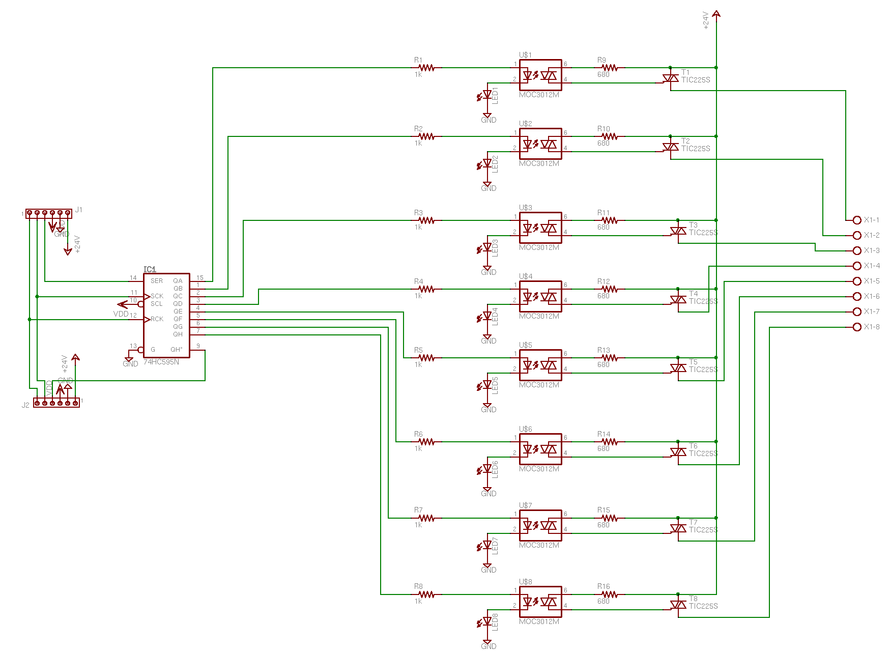
Hi all, I'm trying to design an irrigation system for my house. I have little experience in working with triacs/AC power in general, so could somebody look at/critique this output board schematic for me? Any suggestions/constructive criticism would be much appreciated. I've based the design on others found in these forum threads:
http://forums.parallax.com/forums/default.aspx?f=21&m=151374&g=152043#m152043
http://forums.parallax.com/forums/default.aspx?f=5&m=6127&g=6250#m6250
My specific questions are:
- How do I size the limiting resistor that comes through the optoisolator and triggers the triac via the 24VAC line?
- Are the smoothing capacitors found in Bullwinkle's design completely necessary?
- Is carrying the 24VAC line through edge connectors a feasable idea? If so, what sort of edge connectors/headers do you reccommend? I have no idea how to even begin to choose this sort of component.
- Does anybody have any advice/links on how to build a power supply that will give me the +5V and 24VAC lines that I need from wall power?
My house has a huge (24 station!) system, so the idea is to make three of these smaller output boards and carry the +5V, 24VAC, and control signals for the shift registers via edge connectors, and control the whole mess from a "motherboard" that has yet to be designed that contains the uController, inputs from the power supply, and COM terminal for the sprinkler valves.
The schematic is attached as an Eagle Lite file and as an image....
Thanks!
sch
91K
1749 x 1281 - 34K
Comments
▔▔▔▔▔▔▔▔▔▔▔▔▔▔▔▔▔▔▔▔▔▔▔▔
Chris Savage
Parallax Tech Support
I use an SSR I got from All Electronics, it isn't shown on the site, but call them and ask them if they have an SSR that will run from 3 to 32 volts, they'll find one for you. I use them with no resistor and have no problems.
All Elec (818) 997-1806
In Eagle for the Phoenix connector, use the Library part con-ptr500 AK300/4
Post Edited (originator) : 12/27/2006 6:40:27 AM GMT
Isn't the MOC3012 an optoisolator? The data sheet says "optocoupler." Is optocoupler != to optoisolator? Sorry I'm kind of a noob at this, im still in the middle of my EE education (:
Anyway, the reason I wanted to use one is so that the digital logic would be protected (I hear the large underground networks of wires that feed the sprinkler valves are suceptible to lightning strikes, etc.) The data sheet for the MOC3012 says that its output is not meant to drive a big load directly; hence the triac.
I looked at the datasheet for the SSR that you have in the schematic; and its internal schematic seems to be the same as my MOC/beefy triac setup that I have in the schematic. The only ones that I could find online are like 5 bucks a pop, so since I have a 26 station sprinkler system, the setup I have would save a lot of cash (if it will work) since I do not absolutely need it to be in a tiny package like that SSR.
If you're really interested (you definitely don't have to be spending your time helping me!), here's the datasheet for the MOC:
http://www.fairchildsemi.com/ds/MO/MOC3012-M.pdf
Check out figure 7 on page 5. It describes how to use its output to drive a big inductive load. Looks like I'm going to have to add some extra components.
I was just planning on sourcing the 24V to the sprinkler unit through the output of the SSR/triac/whatever, and the sprinklers are going to have a common ground on a different board that I am designing.
Now for a really stupid question: If I am using AC current, how do you define VDD and GND, and thus define whether something is being sourced or sunk? For example, on that example circuit from the MOC datasheet, does it really matter whether the load is placed above or below the output triac?
I really appreciate your advice on this!
The part number you have is an opto isolated triac(basically an SSR), so just use it eaxctly as I drew the schematic, use maybe 200ohm - 470ohm on the resistor and you'll be fine with 5 volts signal. The triac will turn on the 24ac to your system. This assumes that your system is OK with floating the input if unused, as many 24v systems are set up.
The load can go anywhere in the path, but as I have drawn it, Vss is the same as GND.
Not knowing the current rating of your sprinkler input, I assumed you have looked at it and have deternmined that the part you want to use will have the capacity to supply the current. If the parts are more than $12.50 and lot of work to build it, then get the SSR from All, I just spoke to them, call them and say 3-32vdc input, 15 amp SSR, they have them at 12.50. They can mount without using a circuit board, just run some wires to it. These are way overkill for your project, you could call digikey.com, ask for a tech and tell him what you want as far as an SSR, they will likely have a cheaper solution.
Post Edited (originator) : 12/27/2006 11:57:56 PM GMT