Lynxmotion Hexapod III with Propeller Brain....
Hi.. I finally finished the assembly of my Lynxmotion Extreme Hexapod III with ... what else?? a Propeller brain!!... 
For the servo control.. I am using the servo32.spin object (Thank you very much Beau Schwabe at Parallax for this great object)... this Hexapod is a very good way to test the servo32.spin object since it has 18 servos (6 legs, 3 servos per leg).. and I have to say that the operation of the servos is incredibly smooth even with the Hexapod walking at higher speeds, and when the Hexapod is stationary the servos maintain their positions without jerking or variation of torque... I am very glad with the results of the servo.spin object...
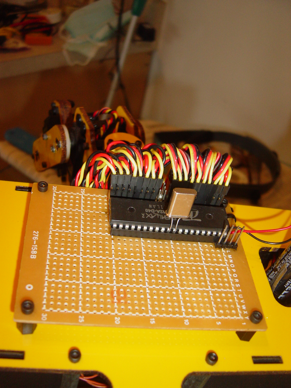
The breadboard is very simple... a row of connectors for the 18 servos... I have yet to add the EEPROM, the crystal socket and regulators, but I have plenty of space on the prototyping board to add more components... I tested the connections from the Propeller to the servos based on the recommendation of using 4.7K Ohms resistors between the Propeller pins and the Signal Input to the servos... but I didn't notice any change for the better or the worse in the servo behavior... perhaps somebody can explain the recommendation for those resistors... I connected all 18 servos directly to the pins of the Propeller (no resistors at all) and it works perfectly...
I attached a picture of the board and a video of the Hexapod in action...
Happy Roboting....
"Propeller.... Unleash the REVOLUTIONs"

For the servo control.. I am using the servo32.spin object (Thank you very much Beau Schwabe at Parallax for this great object)... this Hexapod is a very good way to test the servo32.spin object since it has 18 servos (6 legs, 3 servos per leg).. and I have to say that the operation of the servos is incredibly smooth even with the Hexapod walking at higher speeds, and when the Hexapod is stationary the servos maintain their positions without jerking or variation of torque... I am very glad with the results of the servo.spin object...

The breadboard is very simple... a row of connectors for the 18 servos... I have yet to add the EEPROM, the crystal socket and regulators, but I have plenty of space on the prototyping board to add more components... I tested the connections from the Propeller to the servos based on the recommendation of using 4.7K Ohms resistors between the Propeller pins and the Signal Input to the servos... but I didn't notice any change for the better or the worse in the servo behavior... perhaps somebody can explain the recommendation for those resistors... I connected all 18 servos directly to the pins of the Propeller (no resistors at all) and it works perfectly...
I attached a picture of the board and a video of the Hexapod in action...

Happy Roboting....
"Propeller.... Unleash the REVOLUTIONs"


Comments
how are the legs built? please please more pictures of the mechanics.
bye, ...must go buying servos
Post Edited (Joe "Bot" Red) : 12/27/2006 4:02:35 PM GMT
Thanks for your comments, I'm glad the servo32.spin object is working well for you... There was a bit of effort that went into how that object would work. To answer your question on the 4.7K resistors... This is mainly to help suppress any back emf that might make its way into the controller through the signal line. This is usually more noticeable with long runs (3ft or more) between the servo and the controller. It's not a requirement, but more of a precaution.
acantostega,
Thanks for your comments as well!!
▔▔▔▔▔▔▔▔▔▔▔▔▔▔▔▔▔▔▔▔▔▔▔▔
Beau Schwabe
IC Layout Engineer
Parallax, Inc.
Post Edited (Beau Schwabe (Parallax)) : 12/27/2006 7:26:03 AM GMT
The Hexapod is quite a challenge.
▔▔▔▔▔▔▔▔▔▔▔▔▔▔▔▔▔▔▔▔▔▔▔▔
"If you want more fiber, eat the package.· Not enough?· Eat the manual."········