

Any posiblelities I fry my BS2 pin.
 azmax100
Posts: 173
azmax100
Posts: 173
Hi all.
I am doing some robotic project which require BS2 to drive 2 dc motor through a H Bridge circuit.
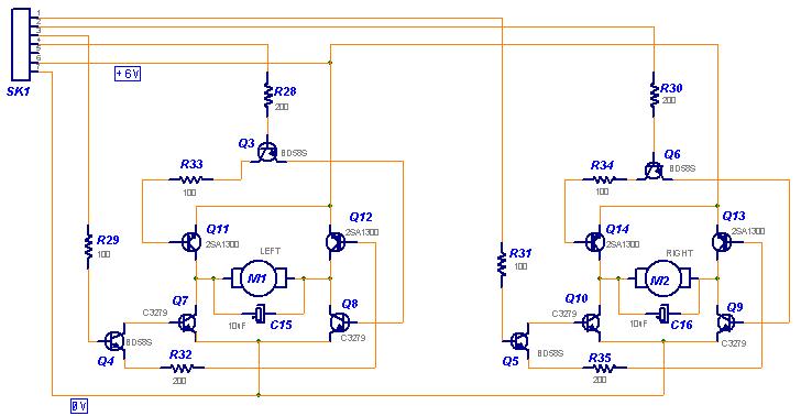
(H Bridge circuit attached). Pin·0 &·1 for left motor, Pin 2 & 3 for right motor. I am supplying the H Bridge
with 7.2v.
The problem is after doing some experiment with High and Low trough PIn·0 to·3 suddenly Pin 3 is not working anymore. I try to shift to Pin 4 but also the same. When I test with multimeter for the output I can't get any output on pin 4 either. I am sure I didn't connect anything to Pin 4. Pin 5 to 7 is ok.
Now I am using Pin 0and 1for left motor and Pin 2 and·5 for right motor.
Is there any posiblelities that I have fry my BS2 pin. If so how can Pin 4 also effected?
Is there any method to check the Pin to see whether it's ok or not.
Please Help!!!
I am doing some robotic project which require BS2 to drive 2 dc motor through a H Bridge circuit.
(H Bridge circuit attached). Pin·0 &·1 for left motor, Pin 2 & 3 for right motor. I am supplying the H Bridge
with 7.2v.
The problem is after doing some experiment with High and Low trough PIn·0 to·3 suddenly Pin 3 is not working anymore. I try to shift to Pin 4 but also the same. When I test with multimeter for the output I can't get any output on pin 4 either. I am sure I didn't connect anything to Pin 4. Pin 5 to 7 is ok.
Now I am using Pin 0and 1for left motor and Pin 2 and·5 for right motor.
Is there any posiblelities that I have fry my BS2 pin. If so how can Pin 4 also effected?
Is there any method to check the Pin to see whether it's ok or not.
Please Help!!!
728 x 378 - 40K
Comments
▔▔▔▔▔▔▔▔▔▔▔▔▔▔▔▔▔▔▔▔▔▔▔▔
- Stephen
Randy
Randy,
Where must I put the diode.If posible please provide the schematic.·Actually I am using the H Bridge board that I·took from my Cybot.But how come Pin 4 also get effected cause I didn't connect anything to the pin.Is there any other·method for me to check the pin other than using Scope cause I don't hve one.I already check with multimeter for the output while make the pin high but there's no reading.
Anyway I will try your suggestion to swap the emitters and collectors on Q4 and Q5.
Thanks & regards.
Merry Christmas!
Forrest has offered an excellent troubleshooting technique. You may want to take it one step further, however.
Perform the test procedure that was noted for EACH of the Stamp pin ports 0-15. Note the results of each test. At the end, arrange the results like this:
·······Out·L················ Out H
·Out A···· Out B···· Out C···· Out D
0 0 0 0·· 0 0 0 0·· 0 0 1 1· ·1 1·1 1
0 1 2 3·· 4 5 6 7·· 8 9 0 1·· 2 3 4 5
Now you will be able to see if an entire bank of pins, or an entire port has been damaged: Pins 0-7 are all "associated", as are Pin 8-15 (see above). Additionally, pin groupings Out A, Out B, Out C and Out D are slso "associated", as noted above. Hopefully, only one pin has been damaged.
Note: Parallax does offer a Stamp repair service (contact them by email or phone), but you must ultimately determine if it is cost effective in your situation. There are, of course, shipping costs involved.
Regards,
Bruce Bates