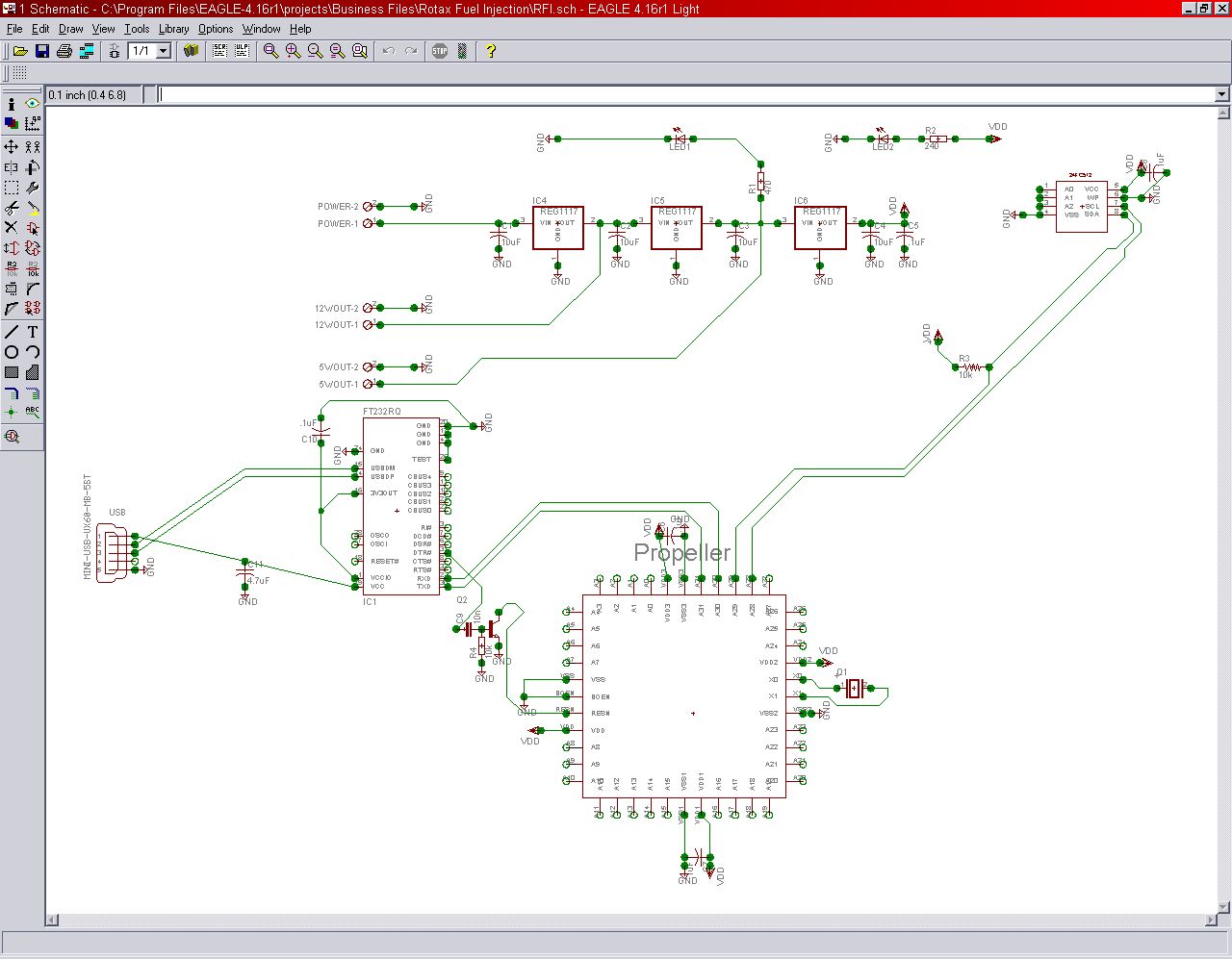
Schematic....using propeller....opinions please.
Ok....so I have drawn a schematic...and would· like to get some opinion....from the peanut gallery. The Parallax guys can comment as well.
Does anyone see anything wrong with this schematic......other that is being messy? The regulators are not correctly labled....they are 12v 5v and 3.3v respectively.
I know some signal lines cross....couldn't be helped....and the transistor for the resn line has some funky routing....but functionally will it work?
James L
Post Edited (James Long) : 12/13/2006 5:10:54 AM GMT


Comments
What kinds of loads will the 12V and 5V outs be used with?
-Phil
They are aux outputs for future sensors like.....prox's...and light current things....no heavy current devices.
James L
Oh, okay. I was a little concerned about your filter caps.
BTW, is there such a thing as a fixed 12V '1117? If not, and you need to use the variable unit, up the output cap to 22uF. And you could go to 22 or 47uF on the 5V supply, too, just for that extra margin. Tantalums all 'round, of course!
-Phil
This give me a wide input voltage range without too many heat issues.
Gavin
Not sure there is a 1117 that is 12 volt fixed.....but there is a fixed 12 volt that is the same package. I have one here somewhere....
I'll increase the Caps....thanks for the suggestions.
James
while I'm waiting for my Propeller-StarterKit I designed a general purpose pcb with cadsoft eagle for future use.
The design is compatible to the StarterKit (i copied the schematic)
- 5Volt and 3V3 Volt Voltage regulators
- A DIL version of the Propeller is used.
- FTDI USB Serial converter FT232R
- 2 DAC (RC-Integrator for PWM)
- 1 ADC (Delta Sigma)
- 2nd EEPROM (I2C Adress 1, switchable between 24LC512/24LC1024 since the 24LC1024 don't use the A2 pin)
- pinheaders for a adapterboard for extensions
A free Version of the layout software can be downloaded on www.cadsoft.de
Please let me know if there are errors in the design
Gtz
Eric
Post Edited (Catweazle) : 12/22/2006 11:02:50 AM GMT
here a picture of the PCB
Size 100x80mm (metric system)
- Pullup resistors for SD/MMC Card interface (I have forgotten them, sorry)
- Added Reset switch
- Pullup resistor for I2C SCL (clock line) added
- additional pinheaders for Reset and power (5Volt) addded
- Empty Adapter board updated (for application)
Zip file contains all updated schematics and layouts (PCBs)
gtz
Eric