

Add Summer and Winter Routines......." DayLight Pool Pump Timer"
 sam_sam_sam
Posts: 2,286
sam_sam_sam
Posts: 2,286
Hi EveryOne
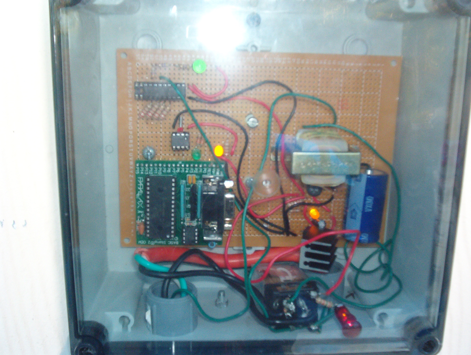
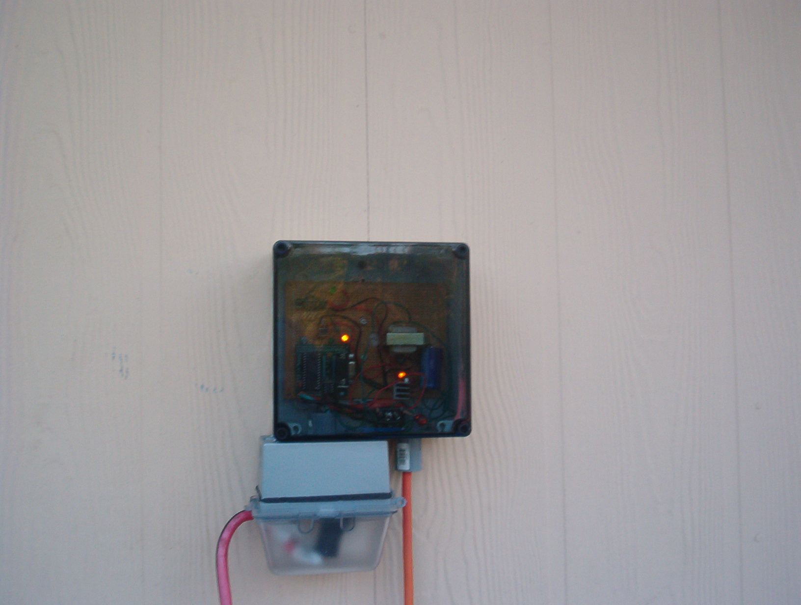
I made this timer for my pool that in my yard and on the box it said
That the pump need to run 4 to 5 hours while the Sun is Out Playing
So this is what i came up with
Here are the photo of the timer and i will post the code later
Sam
▔▔▔▔▔▔▔▔▔▔▔▔▔▔▔▔▔▔▔▔▔▔▔▔
··Thanks for any· ·that you may have and all of your time finding them
·
·
·
·
Sam
Post Edited (sam_sam_sam) : 4/22/2009 4:04:48 AM GMT
I made this timer for my pool that in my yard and on the box it said
That the pump need to run 4 to 5 hours while the Sun is Out Playing
So this is what i came up with
Here are the photo of the timer and i will post the code later
Sam
▔▔▔▔▔▔▔▔▔▔▔▔▔▔▔▔▔▔▔▔▔▔▔▔
··Thanks for any·
·that you may have and all of your time finding them·
·
·
·
Sam
Post Edited (sam_sam_sam) : 4/22/2009 4:04:48 AM GMT

1632 x 1232 - 687K
1632 x 1232 - 771K
1632 x 1232 - 670K
1632 x 1232 - 843K
1632 x 1232 - 837K
Comments
Here· is the code for the· DayLight Pool Pump Timer·below
This might not much of a project but i need a Pool Pump Timer because it says on the box that you need to run the pump
4 to 6 hours while the Sun is Out· Playing
So I thought i need a timer that would come·ON when Sun Came Out Play·and turn off when the Sun when to Sleep
Then i saw Sid's post about how to use a LED as switch
A...ah..h·an
then when sun when to sleep then the pump would rest
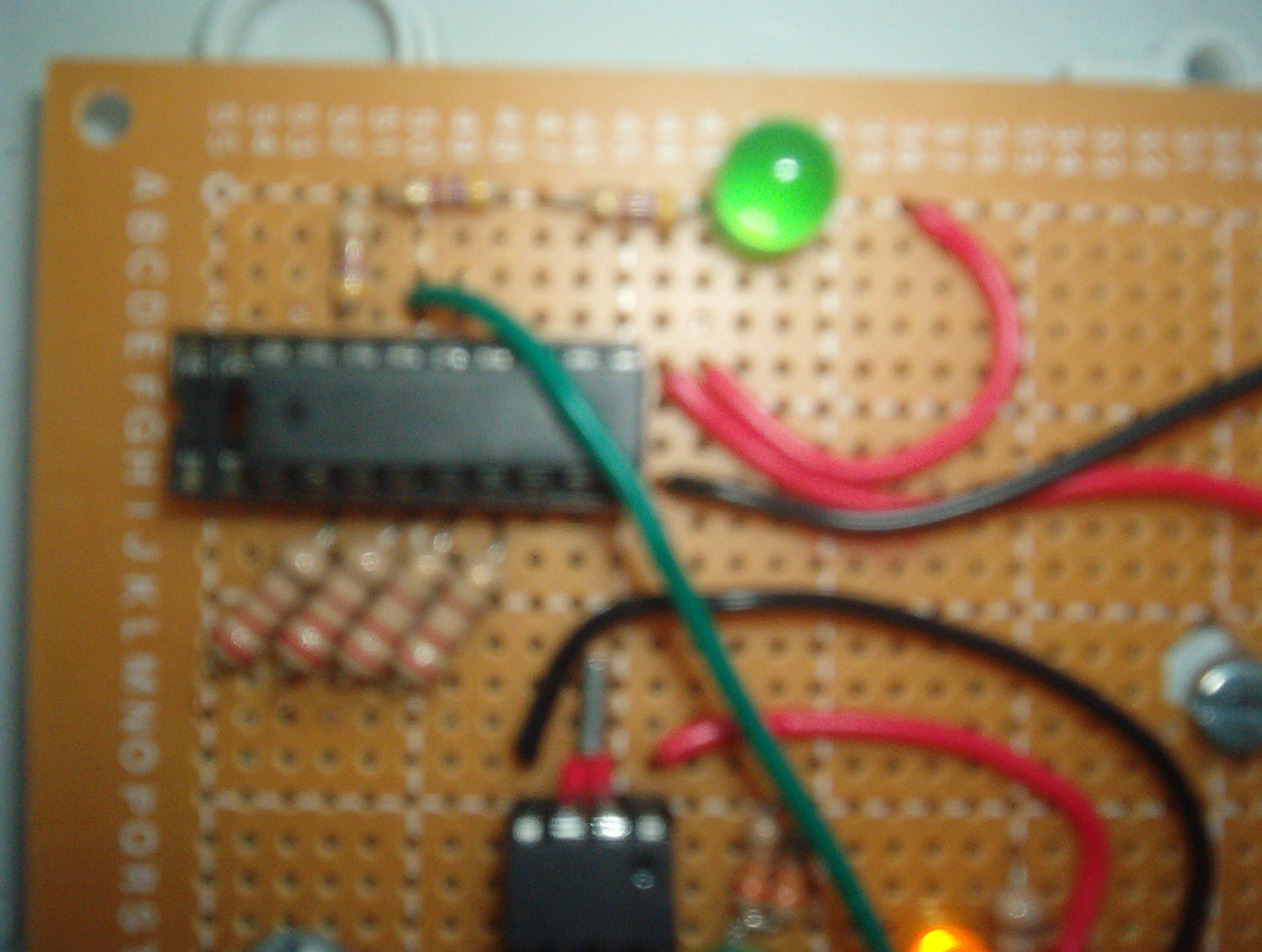
I had been playing with the DS1302 chip so then i played with the Led code that Sid wrote and got that to work and·put the two together
and wa.. la... now we have some thing that work real good it has been running for· last three months and going strong
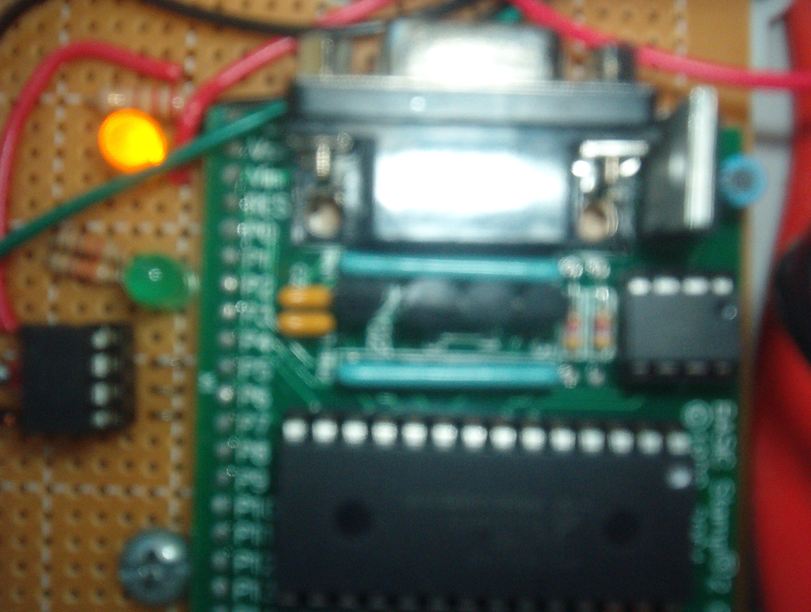
The real reason that i post this is that i want to show how you can use a Led as a switch and a DS1302 and a Basic Stamp
I hope this will help some one that is thinking about how to do same thing
·······These two guys are having some much fun···
Sam
Post Edited (sam_sam_sam) : 12/11/2006 4:01:38 AM GMT
Back in the 70’s (And it still works to this day) my dad built a pool pump timer using a street-light sensor. (I don’t know if you have ever seen one, The are round, grey, and have a photo-cell and stick up on common street lights.) He mounted it to an electrical box and uses it to turn the pool pump on at night, and added an over-ride button that would give 2 hours of ‘pump-on‘ time if the pool was being used during daylight hours. I’m not sure what he used to actually switch on the 1 HP motor. Most likely a relay also.
With your design, you can change it as required! My pool is a small 22” round above-ground and the pump only needs to run about 2 hours a night. Perhaps delayed 5-6 hours after sunset when everyone is asleep or off-peak hours for electric-bill discount rates. An override button is also a useful option and easy to do with your get up. Dad's getup is great also, but I only need to run the pump for an hour or two at night. Despite summer nights being relatively short, my pool size doesn’t justify having the pump on that long.
That’s the beauty of a Basic Stamp as compared to analog circuitry, is when changing parameters it doesn’t usually require swapping out components or major surgery. I can even envision a touch screen for setting times and other bells and whistles. You gotta’ love it!
I wonder if they even sell pool pump timers at the local pool store? Maybe you have product potential?
-Cheers
Thanks for sharing this with me
I wonder if they even sell pool pump timers at the local pool store?
They do but you have to set the time on them and if power go off then you have
reset the time
On the one i built you do not have to set the time if power gose off the
the routine looks to see if the sun is out playing and if so turn on the pump and start timing agian that is why i set it up that way so i have nothing to set
With your design, you can change it as required! My pool is a small 22” round above-ground and the pump only needs to run about 2 hours a night. Perhaps delayed 5-6 hours after sunset when everyone is asleep or off-peak hours for electric-bill discount rates.
You could do this if you changed
IF chg = 0 THEN................................If chg = 1 THEN
GOTO Clock_Run...............................GOTO Clock_Run
ENDIF...............................................ENDIF
Perhaps delayed 5-6 hours after sunset when everyone is asleep or off-peak hours for electric-bill discount rates.
To what you are talking then you do this routine frist
PumpOFF:
Pump only needs to run about 2 hours a night
Then do this routine next
Clock_Run:
The project box is from KELE there web page is at www.kele.com
Sam
Post Edited (sam_sam_sam) : 12/21/2006 9:53:32 PM GMT
A "maintainence" switch so you can override the photocell. You need to turn the pump on at odd times for backwashing, etc.
▔▔▔▔▔▔▔▔▔▔▔▔▔▔▔▔▔▔▔▔▔▔▔▔
Thanks for your reply
I have not learn how to program a SX your are right it may over kill but i buy the BS2 OEM kits that
i put together
·I might learn how to·SX some day but i need something to control my pool pump now and
I·have learning how to program BS2's and there alot more DEMO code on the forum then
for SX chip
As·for the relay
The types that can drive pool pump motors are not cheap but it is well worth it. They typically last longer and need less circuitry and power to drive them.
This is the reason that i use a relay was the cost but the other reason was that i was not sure if this design was going to work or not now that i see that it works very well i will think about some changes
to it
Do you have a solid state relay that would not cost an arm and a leg to buy that can be used with
·a pump motor
·Its a great idea, no doubt, but could use refinement. May I also suggest:
Yes you may suggest this
A "maintainence"
The one thing i going to have to work out about having a "maintainence" switch is bring it out of maintainence·mode and back to the auto mode if the switch is left maintainence mode and until get this routine to work the way i want it to work
switch so you can override the photocell.
I am using an LED instead of an· photocell
·
You need to turn the pump on at odd times for backwashing, etc.
And Thanks for your input in this project
Sam
▔▔▔▔▔▔▔▔▔▔▔▔▔▔▔▔▔▔▔▔▔▔▔▔
Post Edited (Lightfoot) : 12/25/2006 10:17:57 PM GMT
The clock routine that i am using the one i posted at the top of the post·work very well i would like to add
a maint mode to it but i will have to find a switch that will take the wet condistions being outside
dose any one know where i get this type of switch from
The type of switch is one where when you push it is ON and when you let go it off
I found how to wire the switch for the mode i want to use in the online·help
I found a demo code for the button command
' BUTTON.BS2
' Connect an active-low circuit to pin P0 of the BS2. When you press the
' button, the DEBUG screen will display an asterisk (*). The program, as
' shown below, will print an asterisk at the first button press, then
' delay approximately one second (200 x 5 ms PAUSE) before auto-repeating
' at a rate of approximately 100 ms (5 x 20 ms).· Feel free to modify the
' program to see the effects of your changes on the way BUTTON responds.
' {$STAMP BS2}
' {$PBASIC 2.5}
Btn············ PIN···· 0
btnWrk········· VAR···· Byte
Main:
· ' Try changing the Delay value (255) in BUTTON to see the effect of
· ' its modes: 0 = no delay; 1-254 = varying delays before auto-repeat;
· ' 255 = no auto-repeat (only one action per button press)
· '
· ' The BUTTON instruction will cause the program to branch to
· ' No_Press unless P0 = 0
· PAUSE 5
· BUTTON Btn, 0, 200, 20, btnWrk, 0, No_Press
· DEBUG "*"
No_Press:
· GOTO Main
This is what i came up with· i do not know if this will work i have no way of testing this routine
it but it compiles that all that i can tell you now
· PAUSE 5
· BUTTON Btn, 0, 255, 20, btnWrk, 0, No_Press
· DEBUG CR,CR, "maintainence mode"
·· GOTO maint_Run
No_Press:
· GOTO PumpOFF
·maint_Run:
LOW PumpLedOff
hrs· = $00
mins = $00
secs = $00
GOSUB Set_Time
DEBUG CLS, CLS
DO························································ 'This Starts the Pump
DEBUG CR,CR, "PUMP START"
IF hrs = $00 AND mins = $00 AND secs = $05 THEN
GOSUB relay_ON
ENDIF
· GOSUB Get_Time
· DEBUG HOME, HEX2 hrs, ":", HEX2 mins, ":", HEX2 secs
· IF hrs = $00 AND mins = $30 AND secs = $00· THEN
· DEBUG CR, CR, "00:30:00 Elapsed"
· GOSUB PumpOFF
· ENDIF
LOOP
The pump·motor run off of 120 volts it a very small motor it fit in your hand
it might be 2 to 5 amp motor at the most but i will check the motor draw and let you know
Sam
Post Edited (sam_sam_sam) : 12/26/2006 3:50:06 AM GMT
This site has some watertight switches
http://72.14.203.104/search?q=cache:EuRoNm2FLFsJ:www.automationdirect.com/adc/Overview/Catalog/Pushbuttons_-z-_Switches_-z-_Indicators+watertight+button+switch&hl=en&gl=us&ct=clnk&cd=2
▔▔▔▔▔▔▔▔▔▔▔▔▔▔▔▔▔▔▔▔▔▔▔▔
Thanks for the Info
I am going to order parts for that project
Thanks for your help
·This is a cover for the switch
http://web3.automationdirect.com/adc/Shopping/Catalog/Pushbuttons_-z-_Switches_-z-_Indicators/22mm_Metal/22mm_Pushbutton_Accessories/Misc_Tools_-a-_Accessories/ECX1706-5
This is the switch
··http://web3.automationdirect.com/adc/Shopping/Catalog/Pushbuttons_-z-_Switches_-z-_Indicators/22mm_Metal/Non-Illuminated_Pushbuttons_Flush_-a-_Extended/GCX1112
Sam
Post Edited (sam_sam_sam) : 12/26/2006 4:38:05 PM GMT
I am interested in the photocell you used. Could you tell me about it, how you conected it to the stamp (perhaps a schematic), and how you read it with the STAMP?
Thanks
I can find the web page that talks about ·how·a led work as a switch
There maybe someone on the Forum·that knows where that post is
Basicly you
· Led Pin1.......... to P0· Basic Stamp Pin
· Led Pin2 ......... to P1· Basic Stamp Pin
·
·{$STAMP BS2}
'·· {$PBASIC 2.5}
·······················
·····' How you conected it to the stamp
led············ PIN···· 0·············· 'To LED anode
chg············PIN···· 1·············· 'To LED cathode
dly1··········· VAR···· Byte
dly2··········· VAR···· Word
dly3··········· VAR···· Byte
dly1 = 1
dly2 = 50········ ' Here is where you Change·The ·Value to ADJ The Light Level Respone
dly3 = 100
······ ·············· '· File Name··· Dual LED Switch
DO·················· '· Author....·· Sid Weaver
HIGH led············ '· Some changes where made for· this code to work
LOW chg············· '· In My Project I would like to Thank Sid For Posting
PAUSE dly1·········· '· His Code This made this part easer for me to make this
'charge············· '· work
LOW led············· '· This is One LED Switch
HIGH chg
PAUSE dly1
'input
LOW led
INPUT chg
PAUSE dly2··········· 'Changing This Value Will Change The Light Level Respone
DEBUG CR, DEC ? chg·· ' How you read it with the STAMP?
·
Your Code here
PAUSE dly3
LOOP
This is all you need to use a·Led as a Switch
Here is where they show you how t hook this led as a switvh at this web page
at this web page shows to put a resistor on one pin to led to P0 but you do not need if you use this routine
·Perhaps a schematic
·
·Look at Fig. 4. Schematic of a bidirectional LED interface
http://www.merl.com/reports/docs/TR2003-35.pdf
I hope this help you in what you want to do
▔▔▔▔▔▔▔▔▔▔▔▔▔▔▔▔▔▔▔▔▔▔▔▔
··Thanks for any·
·
·
·
·
Sam
Post Edited (sam_sam_sam) : 1/14/2007 9:53:18 PM GMT
there is a link on the parallax.com site to download the book for free.
chapter 7 looks at measuring light
▔▔▔▔▔▔▔▔▔▔▔▔▔▔▔▔▔▔▔▔▔▔▔▔
Magic Smoke Theory of Electronics –
Inside every electronic part there is magic smoke.
The magic smoke is what makes everything work.
If you release the magic smoke, the part stops working!
Post Edited (Mr. Richard) : 1/17/2007 3:19:54 PM GMT
▔▔▔▔▔▔▔▔▔▔▔▔▔▔▔▔▔▔▔▔▔▔▔▔
- Stephen
The link for the Solid state relays is only rated for 3 Amps
You can find some that will handle more amps but when i have look at them
they cost little more than what i want to spend
One way to this would be to use a contactor they are rated for 30 amps
Coil·@ 24 volts These are used in A\C Units
If need help finding this part·I can help you with that
They do not cost alot
·Then you could use a Solid state relay to run the contactor this would work very nice
·I have a project that i will be doing the same thing i will have a 15 amp load @ 115 volts to control with a Basic Stamp
The pump is a 115 volts @ amp un know but it not a big pump it fit in my hand 3 amps maybe
If you need any help doing this·Please·PM me
▔▔▔▔▔▔▔▔▔▔▔▔▔▔▔▔▔▔▔▔▔▔▔▔
··Thanks for any·
·
·
·
·
Sam
Post Edited (sam_sam_sam) : 2/27/2007 10:25:21 PM GMT
I was able to find a 18 amp SOLID STATE_RELAY
http://www.allelectronics.com/cgi-bin/item/SRLY-18/500500/18_AMP_SOLID-STATE_RELAY,_3-15VDC_CONTROL_.html
I am thinking about ordering one these my self and see how well this will work
I will let you know
▔▔▔▔▔▔▔▔▔▔▔▔▔▔▔▔▔▔▔▔▔▔▔▔
··Thanks for any·
·
·
·
·
Sam
Thanks,
Scott
·I do not know for sure but if the drawing 10mA··I would ·think··a transistor should be used
▔▔▔▔▔▔▔▔▔▔▔▔▔▔▔▔▔▔▔▔▔▔▔▔
··Thanks for any·
·
·
·
·
Sam
My electric bill was killing to run the pool pump for fours a day in the winter
I did not want to have to reload the routine after each season so put both routine so I can change from one routine to another just by moving a switch
I also add a cleaning mode to the timer that when the pump is off and the SUN is out playing ·I can just hold another switch and go in to that routine
▔▔▔▔▔▔▔▔▔▔▔▔▔▔▔▔▔▔▔▔▔▔▔▔
··Thanks for any·
·
·
·
·
Sam
Post Edited (sam_sam_sam) : 4/22/2009 4:34:49 AM GMT