Stepper motor speed & Little Step-U
 Vern Graner
Posts: 337
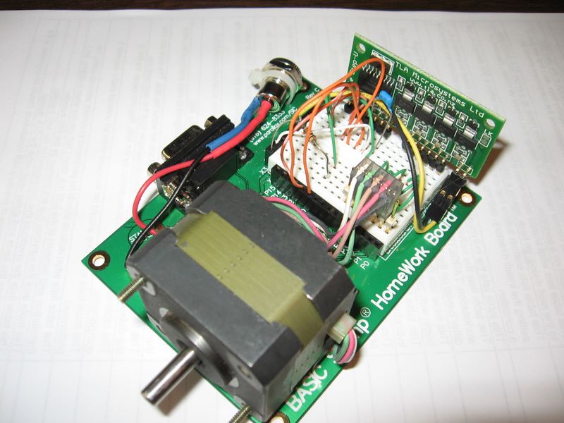
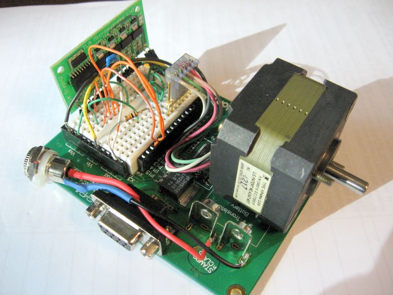
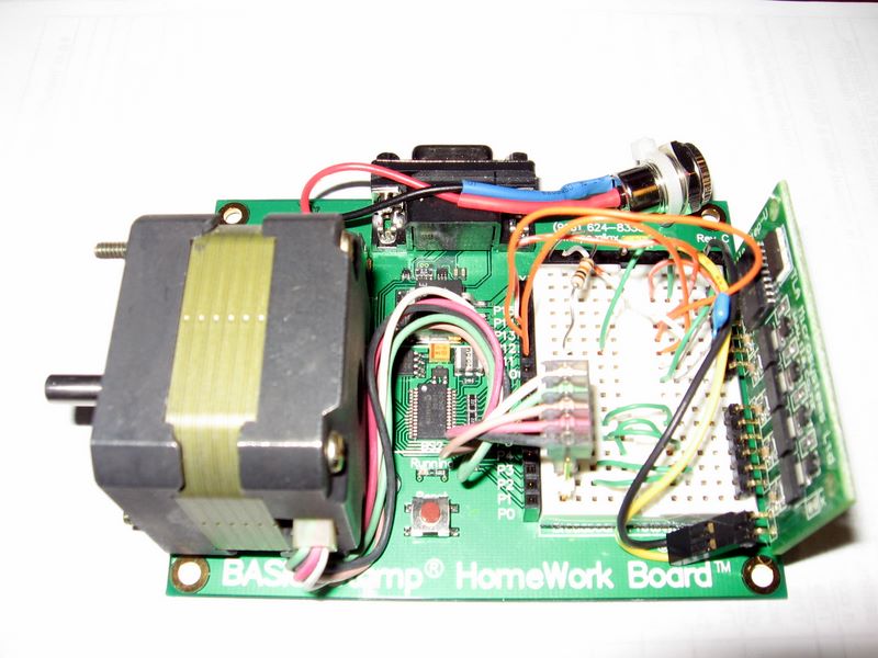
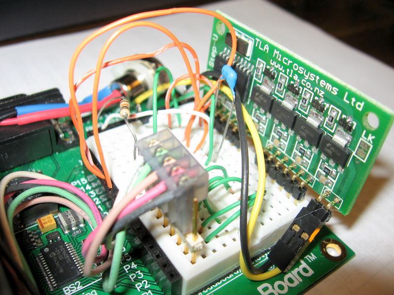
Ok, I have a project I've been working on for a while called The RoboSpinArt Machine. A key component is a rotating platter what holds a paper card. In the prototype machine I used a DC motor and found that, though it spins quite fast enough, it is hard to control the speed precisely. I would prefer to have fine control of it in order to facilitate printing on the rotating paper using one of the Parallax Inkjet printer kits.
So, I read up on stepper motors and controllers, and then I bought the Parallax Little Step U for testing. Based on the specs, in theory, I should be able to get 1500 RPM max out of this unit. Here's the math (in case I missed something):
The stepper motor spins up to about (visual observation guess) 130 RPM and then stops spinning and just "buzzes". I did some reading and found that in order to keep the rotor from "slipping" your can juice up the voltage. So I replaced the 12v 1amp wall wart with a benchtop supply that could deliver 30v at 3 amps. On testing again, I think it got up to about 300 rpm, but still no where NEAR the theoretical maximum of 1500 RPM. (Note: that I am using the Vin to power the motor input on the Little Step U, *not* the 2940-5v regulated voltage from the Homework Board)
So, thinking maybe I had a bad stepper, I tried a couple of other motors I had laying about. All performed substantially the same.
So, anyone with some stepper motor experience have any idea as to what I can do to get a stepper to spin at 1500 RPM with this little controller?
ADVthanksANCE! [noparse]:)[/noparse]
Vern
Added: Video of the effect for those who would like to see it (~1.5m WMV file).
▔▔▔▔▔▔▔▔▔▔▔▔▔▔▔▔▔▔▔▔▔▔▔▔
Post Edited (Vern) : 12/10/2006 5:26:20 AM GMT
So, I read up on stepper motors and controllers, and then I bought the Parallax Little Step U for testing. Based on the specs, in theory, I should be able to get 1500 RPM max out of this unit. Here's the math (in case I missed something):
- The stepper motor is 1.8 degrees per step
- 1.8 degrees per step divided by 360 degrees per revolution = 200 steps per revolution
- The controller max is 5000 steps per second
- 5000 steps per second divided by 200 steps per revolution = 25 revolutions per second
- 25 revolutions per second
- 60 seconds = 1500 RPM

The stepper motor spins up to about (visual observation guess) 130 RPM and then stops spinning and just "buzzes".
 I did some reading and found that in order to keep the rotor from "slipping" your can juice up the voltage. So I replaced the 12v 1amp wall wart with a benchtop supply that could deliver 30v at 3 amps. On testing again, I think it got up to about 300 rpm, but still no where NEAR the theoretical maximum of 1500 RPM. (Note: that I am using the Vin to power the motor input on the Little Step U, *not* the 2940-5v regulated voltage from the Homework Board)
So, thinking maybe I had a bad stepper, I tried a couple of other motors I had laying about. All performed substantially the same.

So, anyone with some stepper motor experience have any idea as to what I can do to get a stepper to spin at 1500 RPM with this little controller?
ADVthanksANCE! [noparse]:)[/noparse]
Vern
Added: Video of the effect for those who would like to see it (~1.5m WMV file).

▔▔▔▔▔▔▔▔▔▔▔▔▔▔▔▔▔▔▔▔▔▔▔▔
Vern Graner CNE/CNA/SSE    | "If the network is down, then you're
Senior Systems Engineer    | obviously incompetent so why are we
Texas Information Services | paying you? Of course,if the network
http://www.txis.com        | is up, then we obviously don't need
Austin Office 512 328-8947 | you, so why are we paying you?" ©VLG
Post Edited (Vern) : 12/10/2006 5:26:20 AM GMT


Comments
·
·· While the Little Step-U lists a 1500 RPM max, the Stepper Motors I have seen top out long before that.· Stepper Motors have a limit at how fast they can spin before they simply start jittering.· Once you try to pass their max rotational speed they will often simply vibrate in place.· This is what you are seeing.· The coils and magnets inside aren’t capable of moving it that fast.· I’m sure the ratings on the controller simply refer to its ability to pulse the coils at that theoretical speed.· I hope this helps.· Take care.
▔▔▔▔▔▔▔▔▔▔▔▔▔▔▔▔▔▔▔▔▔▔▔▔
Chris Savage
Parallax Tech Support
Vern
▔▔▔▔▔▔▔▔▔▔▔▔▔▔▔▔▔▔▔▔▔▔▔▔
▔▔▔▔▔▔▔▔▔▔▔▔▔▔▔▔▔▔▔▔▔▔▔▔
- Stephen
·
·· While there are some facts listed above regarding a flywheel and raising the voltage, the fact is a Stepper Motor doesn’t move as fast as a DC Motor.· The flywheel would certainly help if you used ramping, but would make things worse if trying to jump quickly to a higher speed or even starting from a dead stop to a reasonable speed.· Another method of driving Stepper Motors which can increase performance is called, “Chopper Drive”, but I don’t know that the Little Step-U employs that technique.
▔▔▔▔▔▔▔▔▔▔▔▔▔▔▔▔▔▔▔▔▔▔▔▔
Chris Savage
Parallax Tech Support
When i got my stepu i received a lot of help from TLA, who makes the controller. I never got as far as bumping up the speed, i really didn't need it, but they were willing to provide the info to do it. This was a couple of years ago, so i don't know if things have changed there or not. Anyway, might be worth sending them an email.
www.tla.co.nz
kelvin
·
·· As this is a Support Forum all my replies are attempts to help the original poster.· Everything I posted was to provide the Vern with Knowledge to help him discover why he was unable to get multiple Stepper Motors to reach the speeds mentioned by the controller and what things may or may not work and why.· There is no attempt being made to discount anyone’s offerings of information.· When a Stepper Motor stalls, ramping is always used as an attempt to overcome that, however there is a point up to which it is not required, just like in a DC Motor or Servo.·
▔▔▔▔▔▔▔▔▔▔▔▔▔▔▔▔▔▔▔▔▔▔▔▔
Chris Savage
Parallax Tech Support
www.ams2000.com/stepping101.html
▔▔▔▔▔▔▔▔▔▔▔▔▔▔▔▔▔▔▔▔▔▔▔▔
- Stephen
·
·· Chopper Drive is kind of like PWM for Stepper Motors…Normally you would energize a coil, then the next coil, etc.· In half stepping you can energize multiple coils and get half steps.· Chopper Drive allows you to get more efficiency, and I am told better torque because of it.· The main benefit is power savings and reduced heat on the coils.· Chopper Drive also allows you to run higher voltage supplies on lower voltage Stepper Motors since the voltage is being applied in a duty cycle manner.· Below are two links.· The first shows an implementation of Chopper Drive.· The second provides some Stepper Motor information as well as seeming to discount my understanding of reduced heat when using Chopper Drive (obviously I’m no expert on Steppers).· Take care.
http://home.att.net/~wzmicro/l298.html
http://www.anaheimautomation.com/intro.htm
▔▔▔▔▔▔▔▔▔▔▔▔▔▔▔▔▔▔▔▔▔▔▔▔
Chris Savage
Parallax Tech Support
I have done a lot of research--and very little hands on--and have all but discounted the use of stepper motors in my application except for those areas where rather slow, precise movements are requried. The alternatives, as you and someone else suggested appear to be dc motors with feedback (Hall-effect is my current favorite) and servo motors, also with feedback.
I am looking at the AX-12 servo,·but communicating with it appears daunting at this time, to say the least. (For me, anyway.) However, the AX-12 is VERY intelligent and provides built-in networking for up to 253 AX-12s. (It might be 255, but I remember 253.) The AX-12 servo also has a software-selectable continuous turn mode, but I suspect that once it is selected, you will lose a lot of the intelligence I lauded earlier.
Anyone reading this might take a look at the specifications, linked to above. If you figure out how to easily interface it to a Stamp, I owe you! There is supposed to be a USB to serial at TTL levels device introduced by the AX-12's creator; Robotis, in Japan. If that happens, then interacing to the intelligent and powerful AX-12 may prove rather easy.
--Bill
▔▔▔▔▔▔▔▔▔▔▔▔▔▔▔▔▔▔▔▔▔▔▔▔
You are what you write.
Nice motor! Looks like it can be controlled directly from a stamp using serial communication.( serin / serout )
kelvin
The primary limiting factor in a stepper motor is the inductance of the coil in the motor. It takes time to build up the current (and therefore the magnetic strength) for each step. If the stepping rate is quite slow compared to the time constant of the coil there is no problem. However, as the stepping rate increases the time to build up the magnetic strength becomes less and less. Eventually the field only just starts to increase and it's time to turn
the coil off and proceed to the next step. This explains why a stepper motor has its highest torque when it is stopped and how torque drops away as the speed increases.
Motor datasheets specify the DC resistance and the coil inductance and from that you can determine the time constant (Inductance divided by resistance). So, while the Little Step-U can generate the pulses, the motor itself prevents it from moving at that speed. The (full) motor datasheets will show a speed/torque curve for the motor and you can see the actual maximum speed.
Not being content with the simple time constant speed restriction, we can start throwing in some techniques to improve on that.
It's important to note that the parameter of interest here is current. The magnetic field strength is a function of the current flowing. The faster we get the current to change, the better the performance. On the flip side, we
musn't exceed the current rating of the motor as this generates heat and heat is the enemy of stepper motors.
One technique is called the L/R drive. Here you increase the supply voltage and add a series resistor to maintain the total current flow to be the same as the specified value. For example, if you had a 5V 1A motor, you'd calculate the motor resistance to be 5V/1A = 5 Ohms. If you doubled the supply voltage to 10V and wanted the same current then the total circuit resistance needs to be 10 Ohms. The motor is 5 Ohms, so a series resistor of 5 Ohms would do the trick. Suppose our motor had an inductance of 5mH. The time constant of 5mH / 5 Ohms = 1ms (or a step rate of 1kHz). With the added resistor, the time constant is now 5mH / 10 Ohms = 500us (2kHz). Take the supply up to 25V with a resisor of 20 Ohms and the time constant is now 200us (5kHz).
This is called the L/R drive or the L/xR drive (where x is the how many motor resistances have been added). The last example with 20 Ohms is an L/4R drive.
If you look closely at a datasheet with a motor torque curve, you'll probably find mention of the curve being with an L/4R drive or having a high supply voltage (ie. an L/xR drive). ie. The motor manufacturers use this technique to show their motors in the best way.
The disadvantage of this drive method is that it is very wasteful of power. In the L/4R example, we are taking 25W from the power supply and only using 5W in the motor. The remainder is wasted as heat in the resistors.
The next progression from the L/xR drive is the chopper drive. This uses the time constant of the motor to achieve the same result without the power wastage. If you take the resistor out the L/xR drive but leave the supply the same, it will still take some amount of time for the current to ramp up to the specified value. If you measure the current and turn it off when it reaches that level, it will ramp down again. After a small delay, you can turn it back on and turn it off when it reaches the threshold and so on. This has given you the advantage of the higher voltage without the power dissipation of the resistors. While the idea is simple, the implementation is quite a bit more complex, with its own problems and the Little Step-U doesn't offer this drive method.
Someone mentioned the use of flywheels and/or loading.
This is another characteristic of stepper motors called low speed resonance and varies in effect substantially with different motors. If you imagine a motor taking a single step. The rotor is intially stopped and stable. It then gets
accelerated towards the new position but goes past it and then rocks back and forth a bit before coming to rest at the new position. Now in a multiple step situation, if the timing of the pulses is such that the rotor is not stable at the new position before the magnetism goes away, you can see that it would loose torque very quickly at
that speed. Speeds above and below it are fine. The way to prevent a low speed resonance problem is to damp it out with a frictional load or to have a flywheel that will allow the controller to accelerate through that frequency.
Sorry for the long post, but there were a lot of points brought up that all tie in together. I hope some of it makes sense.
As for Vern's original post. You've probably reached the limitation of the motor that you have. You'll nearly always get better performance from a motor with a low voltage rating and using the L/xR drive than a higher voltage motor. If you don't need low speed torque and defined speed, then a DC motor may be a better option. Otherwise, look at a larger stepper (for torque) and gear it up to gain the speed.
Steve.
Thanks for the post Steve I took alot away from it I didnt know.
Thanks Steve, I very much appreciate being taken back to school with such a clear and concise explanation.
·
·· Thanks!· Learned a little myself!· Take care.
▔▔▔▔▔▔▔▔▔▔▔▔▔▔▔▔▔▔▔▔▔▔▔▔
Chris Savage
Parallax Tech Support