Help me understand a Phototransistor better
I am working on a project based on an article on robot navigation by Jim Ubersetig [noparse]/noparse][url=http://www.rssc.org/newsletter/index.html#1]http://www.rssc.org/newsletter/index.html#1[/url
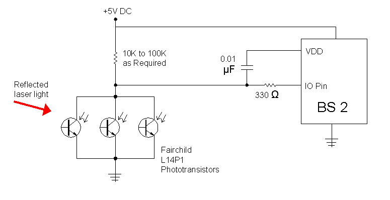
In it he uses a laser to hit reflective targets, and senses the reflected light with a L14P phototransistor, in the circuit image attached.· It is used with a Basic Stamp, and the input is read using a RCTime command.· However, in my case because I want to read barcodes, I need a faster response. I·and am using an analog to ditigal converter on the BS3pe mother board to get my readings.
I've had some electronics training, so I understand the operation of a transistor.· But, phototransistors weren't part of that, and I haven't found·a satisfactory explanation of their function.· I imagine that the light input serves the same as the base current. In Mr Ubersetig's circuit, the 10kto100k resistor seems to just be a pull-up resistor like most input switches used on the stamp... but why the range of values "as needed"?· The directions in Mr. Ubersetig's paper have use simply cutting off the base leads from the phototransistor, but what purpose does this lead have when it is used?
Can anyone recommend a good internet source for a tutorial on phototransistors?· Or perhaps give me some answers directly?
Joe Dunfee


Comments
Check the device datasheets for various graphs and sample uses.
I've seen several examples of no resistor used to limit current between the source voltage and ground through the phototransistor. I would think this is necessary to prevent it from blowing up from too much current... but perhaps I am missing something.
Joe Dunfee
Joe Dunfee
· The Stamp Module will treat anything from 0 through 1.4V as a logic LOW.· Above 1.4V to VDD will be logic HIGH.· I'm not sure if Joe caught what you meant.
Joe,
·· Bear in mind too that an Opto will have the effect of inverting the signal since a high to the LED side will actually swing the Stamp input LOW.· The 10K to 100K range will affect many things, including the input range as well as the speed the line can rise and fall (Slew Rate).· I hope this helps.· Take care.
▔▔▔▔▔▔▔▔▔▔▔▔▔▔▔▔▔▔▔▔▔▔▔▔
Chris Savage
Parallax Tech Support
▔▔▔▔▔▔▔▔▔▔▔▔▔▔▔▔▔▔▔▔▔▔▔▔
- - - PLJack - - -
Perfection in design is not achieved when there is nothing left to add.
It is achieved when there is nothing left to take away.
I know I took some liberties in describing the effect of different resistor values. I couldn't remember exactly what the threshold was for the Stamp inputs, but, in any event, the values I mentioned were really based on a 1.0 volt threshold for ease in calculating them in my head. The actual current for a 10K resistor should be more like 0.36ma and, for a 100K resistor, 36ua. In other words, what's the current required to produce a voltage drop of 3.6V (5.0V - 1.4V) for a resistor of 10K or 100K?
Mike
They're SMD, but·they can be soldered easily enough across two pads of an experimenter board.·
[noparse][[/noparse] The leads are a little tarnished, even though they're still in their protective strip.· Is that why they're 5/$1?· It comes off easily with Tarn-X. ]
** Post Edit **· With a range of 400-1200nm, they have response to most all the visible range into the far I-R.
··········nm
red···· 620-750
orange· 590-620
yellow· 570-590
green·· 495-570
blue··· 450-495
violet· 380-450
Post Edited (PJ Allen) : 12/5/2006 2:27:01 AM GMT