

I'd like to Introduce.....SpinStudio
 parts-man73
Posts: 830
parts-man73
Posts: 830
I've been working on a product for months, and I believe the time is right to reveal it to everyone else in the group. I'd like to introduce SpinStudio.
First, What is SpinStudio?
When I first learned of the Propeller microcontroller, it immediately piqued my interest. I signed up for a user name on the Parallax forums and started discussing the Propeller with other enthusiasts in the months leading up to the release date. Beforehand, I had been using other brands of microcontrollers, but was disappointed by their shortcomings. I quickly saw that the Propeller fulfilled all of those shortcomings and went on to set the bar higher. At the same time, I had been designing circuit boards as a hobby, and I decided on my first project with the Propeller.
I worked long and hard on my first version, trying to fit all the components I desired onto one single circuit board, I wanted access to all the features that the Propeller had to offer, but space on my circuit board was tight. Then an idea struck me, why not a modular system? I threw out my design and started with a clean slate. What evolved from that idea is what I present to you now, SpinStudio.
So what is SpinStudio? SpinStudio is Flexibility.
I have attached a picture of the complete SpinStudio system.
Read on in this thread for more, and thank you for taking the time to read!
Brian
First, What is SpinStudio?
When I first learned of the Propeller microcontroller, it immediately piqued my interest. I signed up for a user name on the Parallax forums and started discussing the Propeller with other enthusiasts in the months leading up to the release date. Beforehand, I had been using other brands of microcontrollers, but was disappointed by their shortcomings. I quickly saw that the Propeller fulfilled all of those shortcomings and went on to set the bar higher. At the same time, I had been designing circuit boards as a hobby, and I decided on my first project with the Propeller.
I worked long and hard on my first version, trying to fit all the components I desired onto one single circuit board, I wanted access to all the features that the Propeller had to offer, but space on my circuit board was tight. Then an idea struck me, why not a modular system? I threw out my design and started with a clean slate. What evolved from that idea is what I present to you now, SpinStudio.
So what is SpinStudio? SpinStudio is Flexibility.
- Say for example you have one of Parallax’s demo boards. You have all the circuitry and connectors present to interface a variety of peripheral devices, such as VGA or RCA video, keyboard, mouse and sound. All of these features are excellent to show off the power of the propeller, and make for a great “out of the box” initial experience. You can dive right in and start developing code. But you have the limitation of having direct access to only 8 out of 32 I/O pins, and a very small solderless breadboard area to prototype with.
- On the other end of the spectrum, there are the PropSTICK, PropSTICK USB and the DLP-PROP solutions. These give you the access to all of the I/O pins and you can supply as much breadboarding space as you desire. But you have to create your own peripheral connections. Which is not always easy, as the connectors for these parts do not fit into a standard solderless breadboard.
I have attached a picture of the complete SpinStudio system.
Read on in this thread for more, and thank you for taking the time to read!
Brian
640 x 480 - 45K
Comments
Here are two definitions of the word studio:
· An artist's workroom
· An establishment where an art is taught or studied
I believe that programming can be an art form, if the programmer is talented enough to make it so. I also think that many elements of the Spin programming language lend themselves to programming as an art. I think of my SpinStudio as a place that experimenters can take their Spin code to perform, or as a workroom for an artist to program his masterpiece.
SpinStudio consists of a main circuit board, permanently mounted to a sturdy Lexan base. The only components on the main circuit board is a regulated power supply, a socket for a 40 pin DIP Propeller, an 8 pin DIP socket for EEPROM memory, and 4 receptacles that accept plug-in modules. Each module has access to 8 I/O lines, Power (both 3.3 and 5 volt), Ground and I2C lines (SDA & SCL).
The peripheral modules plug into the main circuit board, and are supported by plastic posts mounted to the base. All have a specific purpose, for example, one module has all the necessary components for a VGA interface. When the user needs VGA capabilities in the project they are currently working on, it can simply be plugged in. If VGA is not needed in a particular project, it can be unplugged, and those IO lines can be used for a different purpose. Even the programming interface is on a plug in module. Two different programming boards were designed; one that supports a standard serial port for programming, the other is a USB type interface. The whole system is designed with flexibility in mind. Any of the plug-in modules (with exception of the programmer module) can be plugged into any of the receptacles, and only the modules desired need be plugged in. If a fixed purpose peripheral module is not needed, the general I/O type module can be inserted, giving direct access to the 8 I/O pins, Power and I2C.
The flexibility is the key. I plan to offer more plug-in modules in the future. These modules will be fueled by requests by the users. If a new version of the Propeller is introduced, only the main board need be updated, but still maintain compatibility with the same plug-in modules.
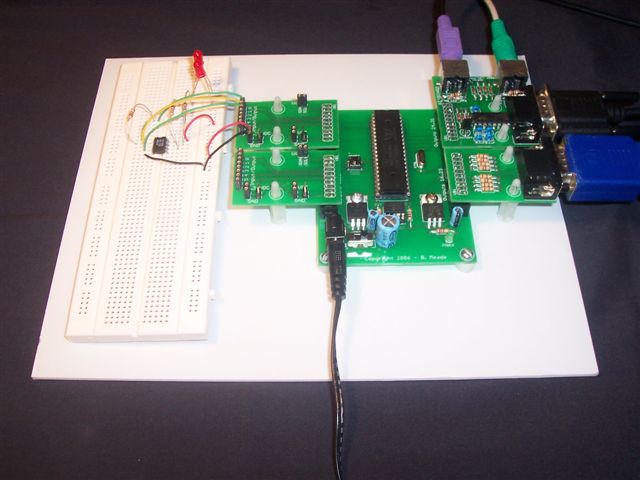
Attached again is the picture of the complete system. With a short explanation of what you are seeing.
The plug in module in the upper right of the photo is the programming module. It also has the interfaces for Keyboard and mouse input.
The lower right module is for a VGA connection
Both modules on the right are for general I/O, direct access to 8 pin, 3.3 VDC, 5 VDC, GND, and both I2C lines.
I have also included a photo of the mainboard with no modules plugged into it.
-ACfishing
▔▔▔▔▔▔▔▔▔▔▔▔▔▔▔▔▔▔▔▔▔▔▔▔
·
Email me at :
Brian@ucontroller.com
In about a week, I will choose my beta-testers and send them out a SpinStudio at no charge. The only thing you'd have to provide yourself is a Propeller, EEPROM, 9 pin(M-F) serial cable, and any addition equipment you'd like to attach to test it with.
I hope to hear from you!
And even if you are not interested in being a beta-tester, I am interested in hearing your comments here on this forum!
Thanks again for taking the time to read this!
Brian
One thing that would be nice to have integrated into your board would be an additional DIP8 for EEPROM/FRAM on the I2C bus. Would potentially save having to mount a module just for additional storage, which is why I added a few on my protoboards that are out to etch.
Is that what you are looking for?
Kova
The general I/O modules have direct access to the I2C lines, and both lines are pulled high via 4.7k resistors. So any additional I2C devices can be easily interfaced. Or if additional EEPROM space is desired, you can put a larger EEPROM into the socket on the mainboard.
Would it make sense to have 2 or more EEPROM sockets on the mainboard?
I also plan to release the pinouts for the I/O connectors, so that users can create their own modules. The connectors are simply 20 pin (2x10) shrouded male headers with 0.1" spacing. You can even plug a IDC connector terminated ribbon cable into the I/O connectors, which may be ideal for mounting in a robot chassis.
Brian
I'm looking toward robotics and automotive projects, so I'm trying to have one standard that lets me do both without too many added modules.
A couple of options that might be good is a four pin header on the main board for the prop plug (I know you have the module but I see the prop plug as being more convinent in a deployed setup, which the board looks like it would be good for) and a screw terminal block for power input (which would better allow for automotive / robotic usage).
I wouldn't mind beta testing one but due to lack of propeller/eeprom that would make it difficult, still trying to decide if I want to try this chip or not.· I've worked with the BS2, Atmega169 (butterfly), and an 8052 variant.
Oh well just my 2 cents.
Both excellent suggestions, and easy to implement.
Any feedback from the members of this forum is of immeasurable value! Keep the ideas coming.
I'd also like to gauge the demand for something like this. Any comments on likelihood that you would purchase something like this are welcomed (don't worry, I won't hold you to it)
Thanks,
Brian
Also what kind of a price range you looking at for your SS? and what kinds of buy options are you looking at? I would assume you will be selling modules individually or as a part of a bundle but what about the mainboard will it be sold separately from the base?
Sorry just tried to rush in some questions at work, hope they make sense.
-Matt
I will definitely post a pinout for the connector. All 4 connectors on the mainboard are similar, Each have the corresponding 8 I/O lines in that group. (i.e. 0-7, 8-15, 16-23, 24-31), both 5 and 3.3 volt, ground and I2C lines. The only variant is the connector for the programming module. The connector has 1 extra pin used for reset(same connector, just fewer unused pins)
I am working on the chapter of the documentation about the connector, and I will post an excerpt as soon as I have it ready (1-2 days)
I don't want to mention an exact price, but I'm going to generalize and say definitely under $100 (you wouldn't believe how fast $2-3 parts add up!). The basic SpinStudio will contain
Also in the future, I'd like to offer other modules, their exact nature and purpose will be driven by user feedback and requests. And with the connector pinout, users can design their own.
Brian
Brian