

Home made SMT
 T Chap
Posts: 4,260
T Chap
Posts: 4,260
After numerous hours of trial and error, reading everything I could find and talking to dozens of people on other forums, here is my process for home SMT. If I could have read this first it woud have been a lot esaier learning curve, so maybe this will help some other people get going. I do agree there may be other preferences and opinions, so feel free to conbtribute.
I use Eagle and really like it, other softwares will have similar features, but I'll speak from Eagle terminology. All parts are very straightforward and easy to do except fine pitch parts like Tssop's, which are .5mm pin center spacing, these are a little trickier at first and will be discussed in more detail. This process does require some initial setup and home made equipment that can be bought very cheaply at most hardware stores. At a minumum, a drill (drill press preferred), some JBWeld, and a jig saw or chop saw is required to build the system. Shortcuts are possible, but I believe the process described achieves excellent and consistent results. I would strongly recommend a convection oven that can be purchased anywhere for around 150. A laser cutting machine is required to make the stencil, if you don't have access let me know as I have a friend with one who would run the stencils for around $25 with fast turnaround. You could email the artwork as described below and have the stencils in no time, even overnight if you are willing to pay overnight charges.
Overview:
A. Generate a stencil for solder paste
B. Apply paste using stencil printer
C. Apply SMT components
D. Reflow boards
E. Clean boards
F. Apply minimal connectors/through hole to test board
Here are the basic concepts that can be expanded later as needed. This setup and process if more for limited production runs.
Generate Stencil
1. Generate schematic/artwork from your PCB software.
2. View SMT pads layers only, then under ULP, select dxf.ulp, generate the DXF file for your pads
3. Create corner markings for you board corners for easier placement and software use later
4. Open the DXF file in some program like Adobe Illustrator, or other program that will allow you to edit DXF files
Note: I didn't like the spacing between 0805 pads in Eagle, so in the editor I made the spacing a little wider to separate the paste a bit more. May not be mandatory.
5. When everything looks like you want it in the DXF, you are ready to make your stencil.
6. Stencil material: stainless is the best, but it is over $175 a stencil at most places. Considering you will likely have several revisions, don't bother with stainless as there is a 6 mil transparency that works just as well. You can get a lot of copies of the mylar stencil for way cheaper than one stainless stencil. All transparancies are not the same. Some melted when lasered. If you want the brand that works great I'll get it and post it later.
Stencil Printing:
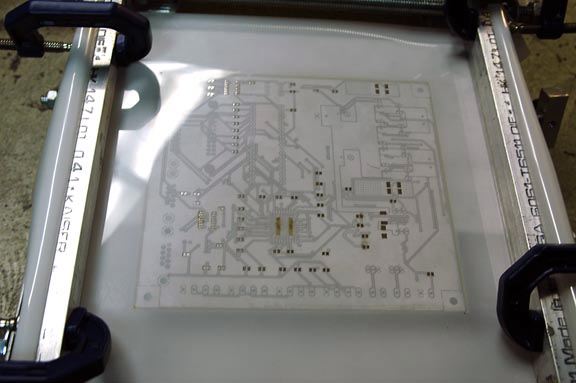
1. Now you have a stencil and are ready to use it, you need a machine to hold the stencil securely to lower the stencil onto the board, and raise it after pasting without smearing. There are some that claim to just tape it down and "peel" it back off after paste, but I did not like that method and wasted some time. You can decide to skip the machine and try tape.
2. Build some type of rigidly hinged machine as shown in the photo. I used silk screen hinges from Mclogon silk screen supply in downtown Los Angeles for $26. The rest of the parts are from a hardware store. I will post more details on the machine if anyone really wanted, but the idea is that the stencil is stretched across a frame held by hinges. The stencil is lowered over the board, and the board is fixed on a table that is adjustable by knobs to align the holes. I used two knobs for X and two for Y, and 4 1/4 28 hex bolts for setting the Z(up down) to get it level. Since the mylar is going to press and fit over the board, the up and down level is not so critical. Attach the stencil to the hinged frame and tighten till it feels firm.
3. Place two few pieces of small double side tape on the bottom of the board, place them on edge for easy removal prior to heating)
4. Position the board against the stencil( under side of stencil), hold in place while lowering everything to table, this will get you closer to alignment. Then when the stencil is snugly over the board, adjust the knobs to get all pads perfectly centered.
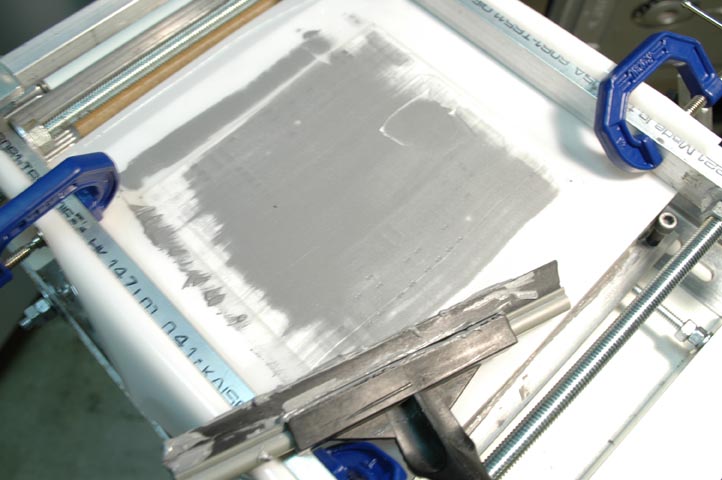
5. Place a good amount of paste on the stencil. I use a cheap flimsy window squeegie that I chopped down to around 6 inches. First get the paste moving around to make sure it is all smoothed out, then just run a thin layer across the board. I like to leave a solid layer, around 1/32 maybe, not really critical, but keep in mind the thickness of the layer will determine the height of the paste "stack' that remains. The stencil itself will regulate the minimum height, so only be concerned with putting too much. Once the layer is nice and even, not to thick, raise the stencil up and examine the remaining paste stacks. If you see something you don't like, you can lower remove it manually and lower the board and replace it, or just clean off the board and start over.
6. Pull board off gently, remove tape pieces from bottom
Apply SMT parts:
1. Get good lighting, a magnifying glass with built in light preferred, plus a hand held magnifier. I use both equally, also I often place one over the other for greater magnification. Set your board where you can work comfortably at a tedious process.
2. Build a home made hand support as shown in the photo, even a gas oven grill may work too. This is very useful and time saving, one wrong move and you smear the board, plus it speeds up the placement by a lot.
3. Have a reference printout of your parts placement. Get easy access to all your SMT parts placed ergonomically. When transferring the part to the board, hold the hand held magnifier under the part while in transit because you will drop parts. Hold the tweezers closer to the part for less dropped parts and better feel.
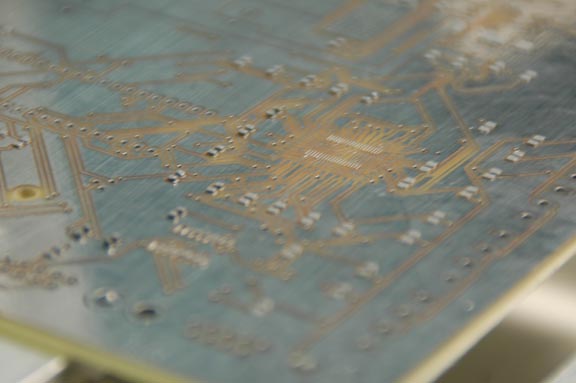
4. Place all parts gently on the paste, give a slight nudge to push the part into the paste to hold it in place. The reflow process has been generally very forgiving on placement, so don't over think the placement as it auto-corrects usually due to surface tension/adhesion(say what?)
5. Once all parts are ready, go back and look at the printout and be sure you put them right, but it is easy to change later if a part is wrong
Reflow boards"
1. Depending on how many boards you do, this process can be as detailed as you want to get. My goal was to fully automate as much as possible, and make it as easy as possible for a not-so-skilled employee(s) to mass produce boards as needed for products. You can actually reflow the components individually with a good heat gun, but that is the least preferred method.
I use this oven which I modified to use an SSR to turn on and off all elements by the PC app.
http://www.pricescan.com/home/items/item701216.asp
I created an app for PC or OSX that can control the SSR directly with or without feedback from a temp sensor. I used the Parallax thermocoupler with K type leads, and just ran the leads right into the oven's front door with no other insulation, so far it has performed very well. I think the analog temp meters for $4 at any grocery store are ok, but are a little slower to respond to change than the thermocoupler, which is fast. In any case you choose, the bottom line is to run the oven for around 3 minutes from startup at 150C/302F. Then head straight to around 220C/428F. You need to track the temp to ensure it gets this hot( or as your paste profile suggests). If you don't want to track the temp, then get a flashlight and simply watch the boards, when it flows, it's flowed! You don't want to cool it too fast but you want to get the temp back down, so I just open the door slightly at first, watch the temp climb down at around 5c max per sec. Then again, read your paste specs. This is just a guideline, don't worry too much about it.
2. Clean the boards, use whatever means to get all flux off if it is needed for your flux type.
3. Inspect all parts with a magnifier. If there are any bridges on a part, here is a good process to remove it:
a. dab a good bit of paste flux(not solder paste) over the problem pins. Run your soldering pencil over all the pins in the area. The flux will act like a frying pan with grease in it, heating all the nearby parts and reflowing the solder that in nearby as well. Run your pencil starting at the IC pin, moving away from the IC, You can see that the solder wants to follow the pencil, so draw the excess solder away from the pins to remove the bridge. Essentially just draw the solder along the traces leading up to the pad. The other idea is to use a wick, but that gets messier and is not as easy in my opinion. The flux will also make pins look night and day better than before, so you may practice this just to get a more pro looking board
b. there is no b
Assemble and test:
1. Add the minimum parts to test the project. In the beginning you may have problems that warrant starting over from scratch, and salvaging parts off a dead board is no fun. Test, and if all is well you can put on the rest of the parts
Well that is too much already for the first installment. If there is further interest, I will go into the fine pitch Tssop parts process which can be done easily with a few extra steps. This is just my view, but after this learning experience, the process is far easier that through hole, not too mention that there are parts out there that are sold only as SMT, so you open up new options for your home fab when you tackle the process.
Set A Pics:
Post Edited (originator) : 12/2/2006 11:36:18 PM GMT
I use Eagle and really like it, other softwares will have similar features, but I'll speak from Eagle terminology. All parts are very straightforward and easy to do except fine pitch parts like Tssop's, which are .5mm pin center spacing, these are a little trickier at first and will be discussed in more detail. This process does require some initial setup and home made equipment that can be bought very cheaply at most hardware stores. At a minumum, a drill (drill press preferred), some JBWeld, and a jig saw or chop saw is required to build the system. Shortcuts are possible, but I believe the process described achieves excellent and consistent results. I would strongly recommend a convection oven that can be purchased anywhere for around 150. A laser cutting machine is required to make the stencil, if you don't have access let me know as I have a friend with one who would run the stencils for around $25 with fast turnaround. You could email the artwork as described below and have the stencils in no time, even overnight if you are willing to pay overnight charges.
Overview:
A. Generate a stencil for solder paste
B. Apply paste using stencil printer
C. Apply SMT components
D. Reflow boards
E. Clean boards
F. Apply minimal connectors/through hole to test board
Here are the basic concepts that can be expanded later as needed. This setup and process if more for limited production runs.
Generate Stencil
1. Generate schematic/artwork from your PCB software.
2. View SMT pads layers only, then under ULP, select dxf.ulp, generate the DXF file for your pads
3. Create corner markings for you board corners for easier placement and software use later
4. Open the DXF file in some program like Adobe Illustrator, or other program that will allow you to edit DXF files
Note: I didn't like the spacing between 0805 pads in Eagle, so in the editor I made the spacing a little wider to separate the paste a bit more. May not be mandatory.
5. When everything looks like you want it in the DXF, you are ready to make your stencil.
6. Stencil material: stainless is the best, but it is over $175 a stencil at most places. Considering you will likely have several revisions, don't bother with stainless as there is a 6 mil transparency that works just as well. You can get a lot of copies of the mylar stencil for way cheaper than one stainless stencil. All transparancies are not the same. Some melted when lasered. If you want the brand that works great I'll get it and post it later.
Stencil Printing:
1. Now you have a stencil and are ready to use it, you need a machine to hold the stencil securely to lower the stencil onto the board, and raise it after pasting without smearing. There are some that claim to just tape it down and "peel" it back off after paste, but I did not like that method and wasted some time. You can decide to skip the machine and try tape.
2. Build some type of rigidly hinged machine as shown in the photo. I used silk screen hinges from Mclogon silk screen supply in downtown Los Angeles for $26. The rest of the parts are from a hardware store. I will post more details on the machine if anyone really wanted, but the idea is that the stencil is stretched across a frame held by hinges. The stencil is lowered over the board, and the board is fixed on a table that is adjustable by knobs to align the holes. I used two knobs for X and two for Y, and 4 1/4 28 hex bolts for setting the Z(up down) to get it level. Since the mylar is going to press and fit over the board, the up and down level is not so critical. Attach the stencil to the hinged frame and tighten till it feels firm.
3. Place two few pieces of small double side tape on the bottom of the board, place them on edge for easy removal prior to heating)
4. Position the board against the stencil( under side of stencil), hold in place while lowering everything to table, this will get you closer to alignment. Then when the stencil is snugly over the board, adjust the knobs to get all pads perfectly centered.
5. Place a good amount of paste on the stencil. I use a cheap flimsy window squeegie that I chopped down to around 6 inches. First get the paste moving around to make sure it is all smoothed out, then just run a thin layer across the board. I like to leave a solid layer, around 1/32 maybe, not really critical, but keep in mind the thickness of the layer will determine the height of the paste "stack' that remains. The stencil itself will regulate the minimum height, so only be concerned with putting too much. Once the layer is nice and even, not to thick, raise the stencil up and examine the remaining paste stacks. If you see something you don't like, you can lower remove it manually and lower the board and replace it, or just clean off the board and start over.
6. Pull board off gently, remove tape pieces from bottom
Apply SMT parts:
1. Get good lighting, a magnifying glass with built in light preferred, plus a hand held magnifier. I use both equally, also I often place one over the other for greater magnification. Set your board where you can work comfortably at a tedious process.
2. Build a home made hand support as shown in the photo, even a gas oven grill may work too. This is very useful and time saving, one wrong move and you smear the board, plus it speeds up the placement by a lot.
3. Have a reference printout of your parts placement. Get easy access to all your SMT parts placed ergonomically. When transferring the part to the board, hold the hand held magnifier under the part while in transit because you will drop parts. Hold the tweezers closer to the part for less dropped parts and better feel.
4. Place all parts gently on the paste, give a slight nudge to push the part into the paste to hold it in place. The reflow process has been generally very forgiving on placement, so don't over think the placement as it auto-corrects usually due to surface tension/adhesion(say what?)
5. Once all parts are ready, go back and look at the printout and be sure you put them right, but it is easy to change later if a part is wrong
Reflow boards"
1. Depending on how many boards you do, this process can be as detailed as you want to get. My goal was to fully automate as much as possible, and make it as easy as possible for a not-so-skilled employee(s) to mass produce boards as needed for products. You can actually reflow the components individually with a good heat gun, but that is the least preferred method.
I use this oven which I modified to use an SSR to turn on and off all elements by the PC app.
http://www.pricescan.com/home/items/item701216.asp
I created an app for PC or OSX that can control the SSR directly with or without feedback from a temp sensor. I used the Parallax thermocoupler with K type leads, and just ran the leads right into the oven's front door with no other insulation, so far it has performed very well. I think the analog temp meters for $4 at any grocery store are ok, but are a little slower to respond to change than the thermocoupler, which is fast. In any case you choose, the bottom line is to run the oven for around 3 minutes from startup at 150C/302F. Then head straight to around 220C/428F. You need to track the temp to ensure it gets this hot( or as your paste profile suggests). If you don't want to track the temp, then get a flashlight and simply watch the boards, when it flows, it's flowed! You don't want to cool it too fast but you want to get the temp back down, so I just open the door slightly at first, watch the temp climb down at around 5c max per sec. Then again, read your paste specs. This is just a guideline, don't worry too much about it.
2. Clean the boards, use whatever means to get all flux off if it is needed for your flux type.
3. Inspect all parts with a magnifier. If there are any bridges on a part, here is a good process to remove it:
a. dab a good bit of paste flux(not solder paste) over the problem pins. Run your soldering pencil over all the pins in the area. The flux will act like a frying pan with grease in it, heating all the nearby parts and reflowing the solder that in nearby as well. Run your pencil starting at the IC pin, moving away from the IC, You can see that the solder wants to follow the pencil, so draw the excess solder away from the pins to remove the bridge. Essentially just draw the solder along the traces leading up to the pad. The other idea is to use a wick, but that gets messier and is not as easy in my opinion. The flux will also make pins look night and day better than before, so you may practice this just to get a more pro looking board
b. there is no b
Assemble and test:
1. Add the minimum parts to test the project. In the beginning you may have problems that warrant starting over from scratch, and salvaging parts off a dead board is no fun. Test, and if all is well you can put on the rest of the parts
Well that is too much already for the first installment. If there is further interest, I will go into the fine pitch Tssop parts process which can be done easily with a few extra steps. This is just my view, but after this learning experience, the process is far easier that through hole, not too mention that there are parts out there that are sold only as SMT, so you open up new options for your home fab when you tackle the process.
Set A Pics:
Post Edited (originator) : 12/2/2006 11:36:18 PM GMT
576 x 383 - 35K
504 x 335 - 65K
722 x 480 - 92K
576 x 383 - 59K
586 x 224 - 56K
Comments
1. Place some small amount of paste over the pads, not too heavy
2. Place the part
3. Heat gun the part( using modified nozzle the create smaller air flow)
4. Lots of flux
5. Draw off flux with pencil
Post Edited (originator) : 12/3/2006 2:53:53 AM GMT
the end product looks very impressive and definitely looks a lot of "moving parts" to make it happen. It sure must've have been very challenging and at the end very contentful.
I was hoping to find some detailed steps for each of the steps you describe here. It will be very helpful useful to folks like me. In addition, can you point to the inner workings of the stenciling "tools of the trade" and the "idiot's step-by-step" process - that will greatly help.
a list of recommended vendors would be a good one to have for reference
I feel once you master this skill, it can be very time saving and satisfying.
Nice work!
▔▔▔▔▔▔▔▔▔▔▔▔▔▔▔▔▔▔▔▔▔▔▔▔
"any small object, accidentally dropped, goes and hides behind a larger object."
ALIBE - Artificial LIfe BEing. In search of building autonoumous land robot
http://ALIBE.crosscity.com/
·
http://forums.parallaxinc.com/www.manncorp.com/
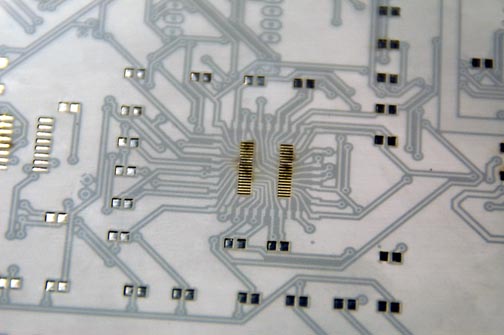
At their site you can see what a $2800 stencil printer look like. In all honesty I'd still build my own. The cheapest oven they have(less inside space that the Quisinart mentioned earlier) is $4800. I have to wonder who really pays that. Some people don't use stencils for simple projects, you can get Kesters solder paste in a syringe and place it where you want. That is the quickest start up, but not reccommended for cranking out boards on a regular basis. Digikey has the parts for Kesters, you need the syringe, the needle and a plunger(all 3 parts). I think it is around $80 to get set up that route. I prefer paste in a jar, at around $40 that will last a while. You recover all the unused portion and put it back in the jar. You can go to stencilsunlimited.com to see some further tutorials, the owner is a nice guy as well, I just prefered to home brew my setup. Unless you are doing super tiny parts like the tssops or similar, most 0805 size resistors and caps are quite easy and fast. Soic IC's are very easy as well. I haven't had but one fault out of quite a few runs boards, and that was a cap that rotated 90 degrees in the oven. I my only real problems were that some dried flux was conducting. Being new to the process, it took a while to discover the problem. I fixed one photo that was not showing correctly, it is a fine pitch IC, Tssop, and the method I used on it is to first lay some paste with a tiny screwdriver over the pads, then place the IC, and heat it till it flows. After it flows I like to run flux over it and clean it up, and draw off any excess solder if any. Once you get some practive, you will place the correct amount of paste most of the time, not needing to fix much.
If you can be more specific with what you want to know I'll try to answer some stuff later tonight. I am not quite clear what you meatn by "tools of the trade". The typical professional setup would consist of a stencil printer, a stainless stencil, some paste, maybe an automatic squeegie but some factories still paste boards manually. The oven are important as you can program your processor or software to run the precise therma; profile each time. I created an SX288 based board that you can either use as standalone(LCD), or with USB2serial to a PC. Credit to Bean for the majority of the code, I only adapted his code to get it into the computer. I prefer the computer version, as it allows a lot of flexibility for drawing the curve, plus it will graph the temp pots in real time or after the fact for some eye candy. It is like taking the space shuttle to Vegas, certainly overkill just for a few boards. With a timer and a good convection(must get to 420F), you can do just fine for now.
The first step tp tackle though is you stencil generation. Here is an example of what I did that we produced the laser>mylar stencil from. The laser only likes outlines, as in cad or illustrator type files, so it can cut line by line, it doesn't cut from a jpg.
This is a plug for my business.· However, I think it is relevant because our main goal is to help people to learn how to use smt components in their design.· Anyways, we are providing 8.5"x11" mylar stencils for $20.· They are just like the ones you all are using in your designs on this thread.· I use them to make all my gps loggers and other products.· They are super handy and now from our service are super cheap.
▔▔▔▔▔▔▔▔▔▔▔▔▔▔▔▔▔▔▔▔▔▔▔▔
Regards,
Ryan O'Hara
www.ohararp.com