

Will it go, or will it blow?
 jhoyoza
Posts: 72
jhoyoza
Posts: 72
Hello again,
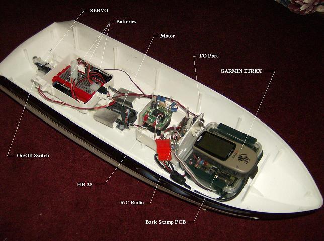
I’m thinking if I run it by this forum first, it may save me the cost of another BS2. I’m interested in knowing if the circuit (below) will indicate to me when the batteries have fallen below 8 Volts on my autonomous-toy-boat project. I do realize that they do sell low-voltage-detectors, however I’m wondering if I could try this method instead. I will use a visual indicator on the boat to signal that it is time to bringing the boat home before we run out of gas. So to speak.
I’m discovering some interesting results when looking at time verses load. I’m using rechargeable 9.6V NiCad batteries. (2 in parallel @ 1600 Mah total) When the batteries are fully charged I get ~11.5+ Volts initially. After a running the motor for a while, the voltage ultimatley reduces. When the voltage drops below ~7.5 volts, I begin to have system problems. I can no longer power the drive-motor at higher RPMS and the radio override system becomes weak and sluggish.
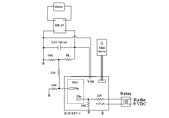
In this circuit, I designed, (Maybe, it will show I should have taken up short-order-fry-cooking as a hobby instead!) when the supply voltage is 12 VDC the output measures 1.7 volt at the BS2 pin. As the battery supply voltage approaches 8 volts the output drops to 1.3 volts thus passing the TTL threshold creating a low input signal? Perhaps a Schmitt trigger, or diode may be helpful? Perhaps the whole thing is just to unstable and obviously futile? (I have a Bs2px if that matters or useful? I do however, prefer to stick with a BS2.)
The NiCad’s also power the BOE board and I don’t understand current flow well enough to figure out which direction it may actually be flowing. I’m not sure if the circuit is will draw excessive current from the BS2 and/or BOA? Also, the fact that the 9 VDC circuit is not isolated from the 5VDC circuit worries me? (In the 9V-radio-circuit, it has a separate power supply and I used relays to isolate the voltages.) Maybe removing the pull-down resistor and adjusting resistor values is the better way to go? Perhaps I can use a transistor with a predictable threshold, or perhaps I’m just going to have to break down and buy a low-voltage-detector-chip? Oh No! Not that!
Thanks and any help will be greatly appreciated.
-J
P.S. I hope I didn't just win the dumbest question of the year award.

For a whole lot of fun! go to: http://www.falstad.com/circuit/
(This thing is great to play with. Anyone can make circuits, and guaranteed not to burn the house down! - I found it on another post by Chris Savage I think - and would like to thank him or who ever else suggested it!)
After the Java window pops up:
Click on file, then import. Then paste in text (below) and click import.
$ 1 5.0E-6 12.185319768402522 54 5.0 43
v 272 48 496 48 0 0 40.0 12.0 0.0
r 272 144 400 144 0 1000.0
r 400 144 496 144 0 8000.0
w 272 48 208 48 0
g 208 48 208 80 0
v 208 336 400 336 0 0 40.0 5.0 0.0
g 208 336 208 368 0
r 400 256 400 336 0 10000.0
x 375 365 391 365 0 18 +5V
x 403 32 419 32 0 18 +12 VDC - 8.9 VDC
x 131 260 147 260 0 18 BS2 pin
w 272 144 272 48 0
s 496 48 496 144 0 false false
w 400 256 208 256 0
r 400 256 400 144 0 220.0
x 276 399 292 399 0 16 BOA REV C
o 13 64 0 3 5.0 9.765625E-5 0
Try changing the 12V source (up top just right click on it) to 8 volts and see the voltage reduction indicated on the scope below?
A good question might be how does one correctly represent a BS2 pin and a BOA in this simulator?
Post Edited (jhoyoza) : 12/2/2006 12:12:58 PM GMT
I’m thinking if I run it by this forum first, it may save me the cost of another BS2. I’m interested in knowing if the circuit (below) will indicate to me when the batteries have fallen below 8 Volts on my autonomous-toy-boat project. I do realize that they do sell low-voltage-detectors, however I’m wondering if I could try this method instead. I will use a visual indicator on the boat to signal that it is time to bringing the boat home before we run out of gas. So to speak.
I’m discovering some interesting results when looking at time verses load. I’m using rechargeable 9.6V NiCad batteries. (2 in parallel @ 1600 Mah total) When the batteries are fully charged I get ~11.5+ Volts initially. After a running the motor for a while, the voltage ultimatley reduces. When the voltage drops below ~7.5 volts, I begin to have system problems. I can no longer power the drive-motor at higher RPMS and the radio override system becomes weak and sluggish.
In this circuit, I designed, (Maybe, it will show I should have taken up short-order-fry-cooking as a hobby instead!) when the supply voltage is 12 VDC the output measures 1.7 volt at the BS2 pin. As the battery supply voltage approaches 8 volts the output drops to 1.3 volts thus passing the TTL threshold creating a low input signal? Perhaps a Schmitt trigger, or diode may be helpful? Perhaps the whole thing is just to unstable and obviously futile? (I have a Bs2px if that matters or useful? I do however, prefer to stick with a BS2.)
The NiCad’s also power the BOE board and I don’t understand current flow well enough to figure out which direction it may actually be flowing. I’m not sure if the circuit is will draw excessive current from the BS2 and/or BOA? Also, the fact that the 9 VDC circuit is not isolated from the 5VDC circuit worries me? (In the 9V-radio-circuit, it has a separate power supply and I used relays to isolate the voltages.) Maybe removing the pull-down resistor and adjusting resistor values is the better way to go? Perhaps I can use a transistor with a predictable threshold, or perhaps I’m just going to have to break down and buy a low-voltage-detector-chip? Oh No! Not that!
Thanks and any help will be greatly appreciated.
-J
P.S. I hope I didn't just win the dumbest question of the year award.
For a whole lot of fun! go to: http://www.falstad.com/circuit/
(This thing is great to play with. Anyone can make circuits, and guaranteed not to burn the house down! - I found it on another post by Chris Savage I think - and would like to thank him or who ever else suggested it!)
After the Java window pops up:
Click on file, then import. Then paste in text (below) and click import.
$ 1 5.0E-6 12.185319768402522 54 5.0 43
v 272 48 496 48 0 0 40.0 12.0 0.0
r 272 144 400 144 0 1000.0
r 400 144 496 144 0 8000.0
w 272 48 208 48 0
g 208 48 208 80 0
v 208 336 400 336 0 0 40.0 5.0 0.0
g 208 336 208 368 0
r 400 256 400 336 0 10000.0
x 375 365 391 365 0 18 +5V
x 403 32 419 32 0 18 +12 VDC - 8.9 VDC
x 131 260 147 260 0 18 BS2 pin
w 272 144 272 48 0
s 496 48 496 144 0 false false
w 400 256 208 256 0
r 400 256 400 144 0 220.0
x 276 399 292 399 0 16 BOA REV C
o 13 64 0 3 5.0 9.765625E-5 0
Try changing the 12V source (up top just right click on it) to 8 volts and see the voltage reduction indicated on the scope below?
A good question might be how does one correctly represent a BS2 pin and a BOA in this simulator?
Post Edited (jhoyoza) : 12/2/2006 12:12:58 PM GMT

Comments
http://www.bobblick.com/techref/projects/a2d555/a2d555.html
...which you may want to check out if you're interested in actual voltage readings. In any case, the 'clever factor' of your design is a 10!
▔▔▔▔▔▔▔▔▔▔▔▔▔▔▔▔▔▔▔▔▔▔▔▔
Roger Pierson
Senior Electronics Technicain
DTI Assoicates
www.emesys.com/BS2rct.htm#B_voltage
You would need to change the parameters (smaller capacitance for shorter RC) in order to use it with the BS2px.
There is no danger to the input pin when the resistor value is large (like 680kohms in the example).
▔▔▔▔▔▔▔▔▔▔▔▔▔▔▔▔▔▔▔▔▔▔▔▔
Tracy Allen
www.emesystems.com
Tracy, I did previously bump into the RCTIME command in the Basic-stamp reference manual. A great feature! I couldn’t figure out how to make it do what you outlined! And with code and component values too! Thank you. The beauty of the command is it only takes a couple of parts and the code is short and sweet. I think it is the way to go! I may possibly be able to live with log scales and reduce code even further. However, I can’t for the life of me, figure out how to use a 681K resistor with the analog circuit above.
I see huge momentary voltage-drops during motor-speed changes and/or servo and relay usage. My thoughts are to live with false alarms as they will be monetary too. That is, until the voltage can no longer bounce-back. I could log data and calculate an average, but that takes more code. I’m starting to realize the handicap of not being able to multi-task. (The GPS unit is powerful, and is what actually provides the intelligence. In essence I am multitasking.) Still, I’m at the limits of the remaining code-space, practical time-delays, and the radio-override is costly in terms of program-space, processor-usage and voltage-variations.
Much appreciations to everyone!
Knowing how one might represent the basic-stamp pin in the circuit simulator (Located at: http://www.falstad.com/circuit/ ) would be very great! Does anyone here know how to do that?
Some Ideas...
Smooth them out with capacitors, and isolate your battery monitor using a diode and capacitor. The cap and diode will hold the sense voltage node for what ever period you need to eliminate false alarms.
Say you have 12V that draws down to 7v for 2 seconds on motor startup. A diode from the supply to your ADC or voltage sensing device with a small capacitor resistor network to hold the voltage while its read slowly bleeds out the resistor, the cap is recharged when the high current draw stops basically averaging your battery voltage if you want to call it that.
You could as well use a sense resistor to sense high current draw and lower the threshold of the low battery indicator or eliminate the signal during high current draw so you only trigger the low battery during low draws.
Programming wise, you could just monitor and time the low battery condition. If it lasts for 10 seconds or whatever then trigger the low battery indicator.
▔▔▔▔▔▔▔▔▔▔▔▔▔▔▔▔▔▔▔▔▔▔▔▔
Think Inside the box first and if that doesn't work..
Re-arrange what's inside the box then...
Think outside the BOX!
·
·· One thing that catches my eye is that you have a resistor divider formed by the 10K and 8K resistors.· This would seem to want to give a slightly higher than ½ VCC tap, but it is complicated by the 220 Ohm and second 10K resistor which effectively create a resistor divider of around 5K/8K (not counting the 220 ohm resistor).
·
·· Another thing is running the Relay directly from the I/O pin.· I would recommend switching it via a transistor (see attachment) and be sure to include the diode shown across the Relay coil.· Lastly, running the HB-25, Servo, Radio and controller all from the same power source could give you problems if the Battery isn’t up to handling peak loads on demand.
·
·· I assume this is the intent of the voltage divider, perhaps to detect a low battery condition?· If so I would recommend putting in a trimmer pot in place of the divider so that way you could dial-in your exact voltage output for low battery and match it to the 1.4V threshold of the BASIC Stamp.· I hope this helps.· Take care.
▔▔▔▔▔▔▔▔▔▔▔▔▔▔▔▔▔▔▔▔▔▔▔▔
Chris Savage
Parallax Tech Support
Post Edited (Chris Savage (Parallax)) : 12/5/2006 12:59:02 AM GMT