

HandCarved_PCB
 bambino
Posts: 789
bambino
Posts: 789
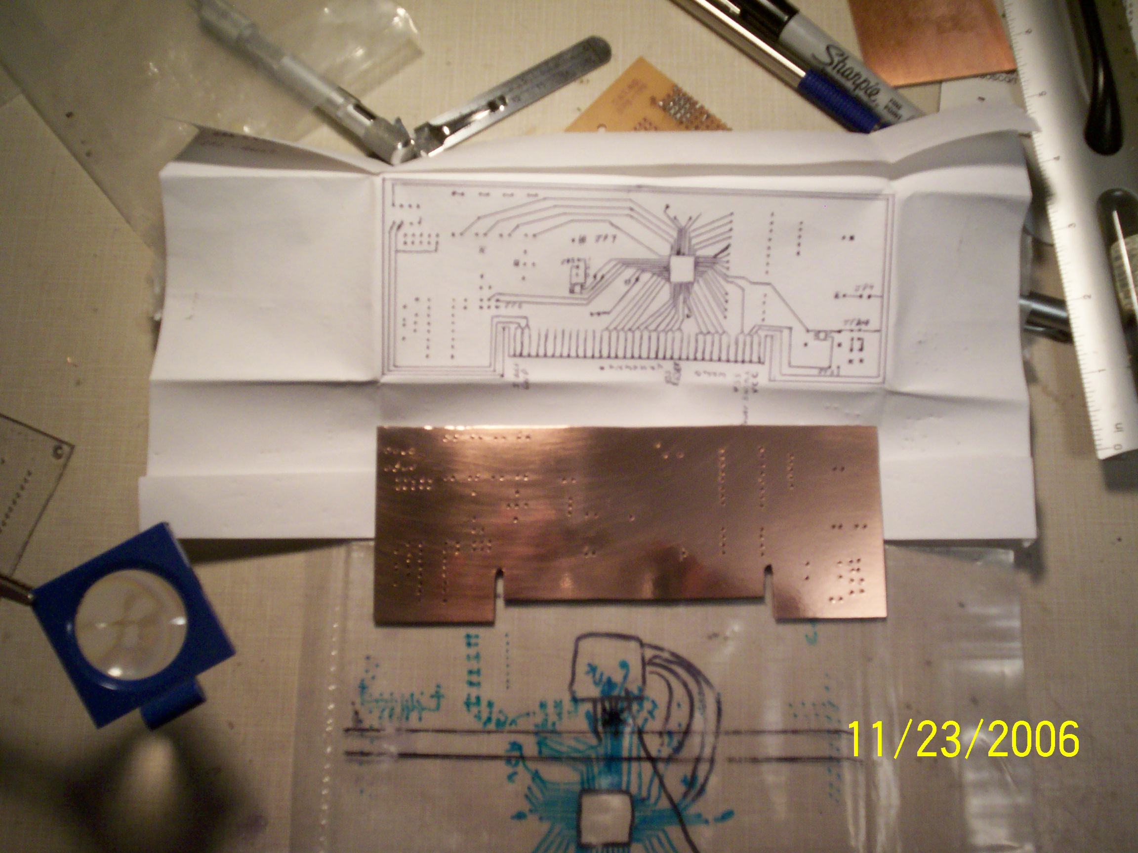
Ten minutes into the etching process I noticed the metal under some of my pen strokes was getting ate away by the etching solution. I terminated the bath and found the board still 90 % shorted to the ground plane. However the pads for the Prop where already etched out so I was afraid to repaint and continue etching.
Not wanting to spend another day reading about the Prop on this forum without having one of my own I BROKE OUT THE HOBBY KNIFE COLLECTION.
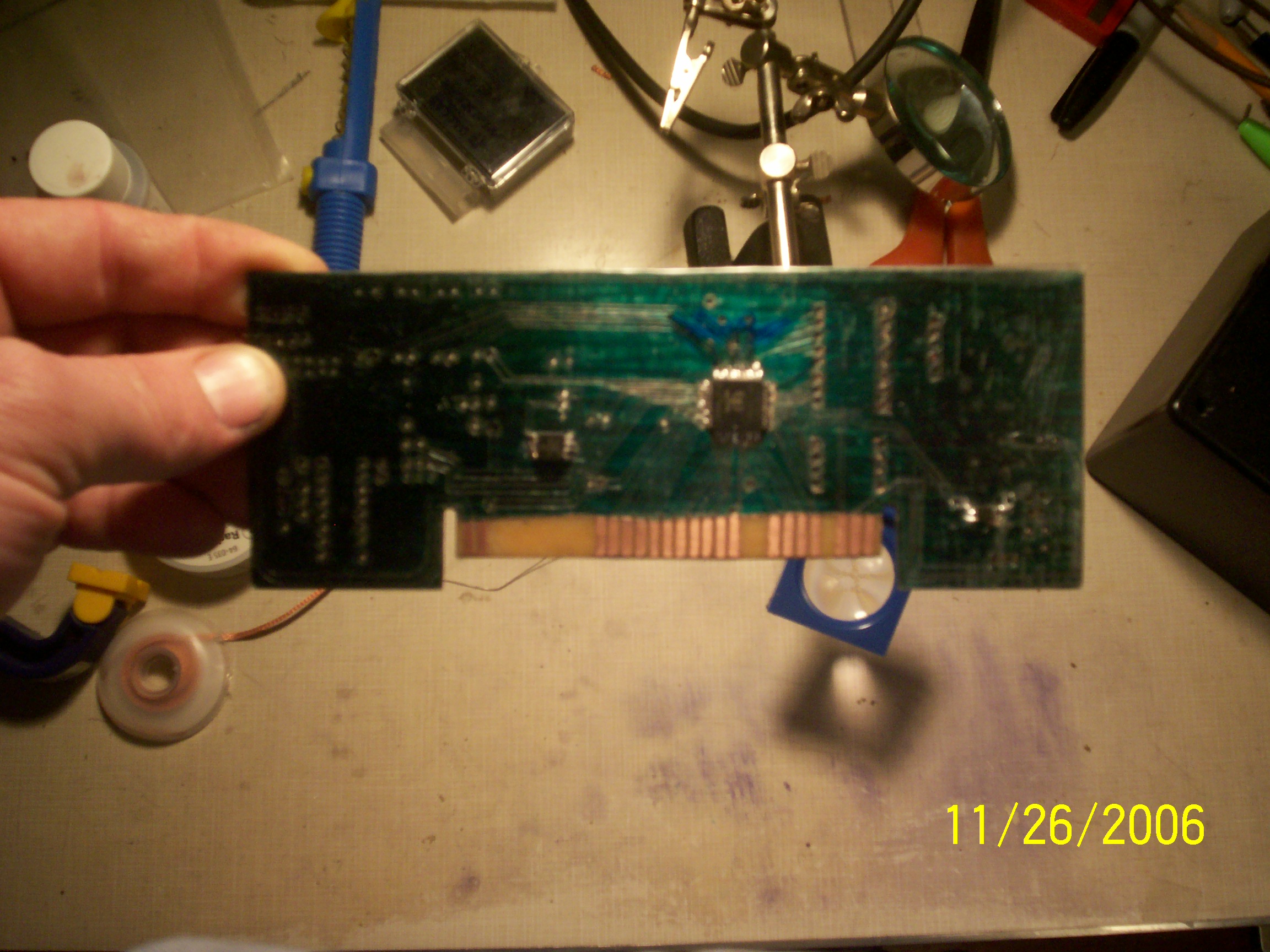
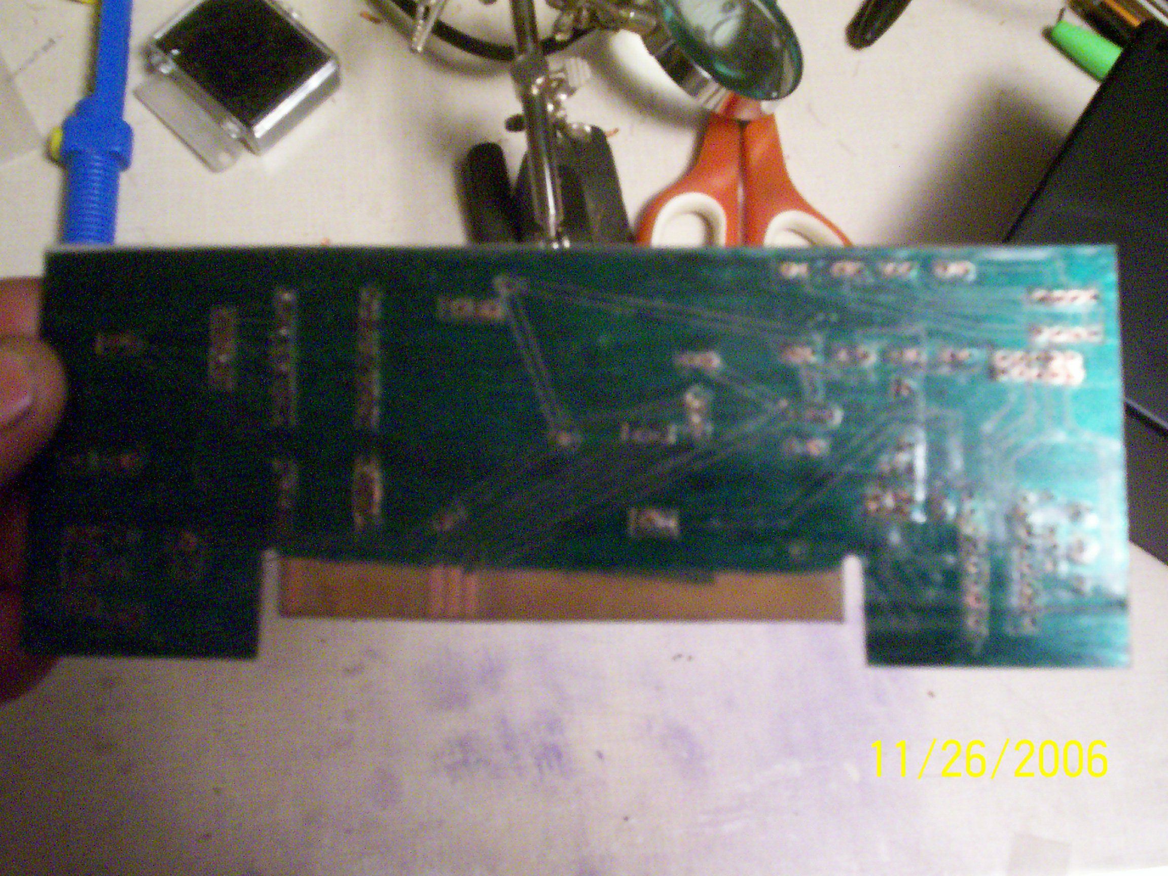
Only one one trace didn't Ohm out(the RX line), But It's repairable!
It shouldn't be long now.
Thanks again to Parallax, Chip, and the good folks in this forum
Not wanting to spend another day reading about the Prop on this forum without having one of my own I BROKE OUT THE HOBBY KNIFE COLLECTION.
Only one one trace didn't Ohm out(the RX line), But It's repairable!
It shouldn't be long now.
Thanks again to Parallax, Chip, and the good folks in this forum
Comments
At times I think using a dremel tool and cutting freehand after laying out the parts with and overlay of paper might just complete a small job faster.
I have several Beam projects that are just too small to bother with photo etch and chemicals and I have not found a way to combine them into one image either.
BTW, I drill all my holes by hand, even when there are several hundred.
It seems that using a pin vise and a drill are faster and I have more control that an electric drill.
I just take the board to Starbucks and drill while I am having moring coffee.
As a journeyman carpenter, I learned that no matter how much automation there is; there is always a place for the handcrafted details.
▔▔▔▔▔▔▔▔▔▔▔▔▔▔▔▔▔▔▔▔▔▔▔▔
"If you want more fiber, eat the package.· Not enough?· Eat the manual."········
Sid
▔▔▔▔▔▔▔▔▔▔▔▔▔▔▔▔▔▔▔▔▔▔▔▔
Sid Weaver
Don't have VGA?
Newzed@aol.com
·
I've always drawn my circuit boards by hand, But until this Thanksgiving I never thought of doing it this way.
I drill all my holes too. I have a little hand tool with bits in the handle and it really makes my "hurry up and wait day" go by fast.
Not fimiliar with your term "beam", If your refering to lining up the lines on double-sided copper, I drill my through holes before drawing my lines, that gives me a reference to go by when I flip the board.
Over all it was, and still is fun to see it come together.
I am not out of this one yet though.
But I am just a trip to radio shack away from communicating with the magic smoke inside the chip
I used to clear up remaining shorting whiskers on home-etched boards by charging a capacitor, then discharging it between the shorted traces. Poof! Maybe not the best way to do it but probably the fastest!
I also used to draw my circuit chip layout pattern on a predrilled perforated epoxy board, then use it as a template to predrill the copper board. It really worked well - with the positioning template, I could drill dozens of holes a minute - zing, zing, zing, zing... Then I'd draw the mask on the copper, using the holes as indexing marks.
The Gootee name comes from his creator.. it is basically a method where you print your design on a laser printer (NOT inkjet printers!!) using cheap deskjet paper and then you iron the design into a clean PCB.. since the toner is basically microscopic plastic particles.. it melts into the PCB... then you remove the paper by soaking the PCB in water... and Viola! I also tried different types of transparency sheet for projectors... and if done properly.. it leaves clean toner traces and it requires no PCB soaking ... you just peel it off after cooling down...but it is more difficult to find the right transparency..
For etching... I found that one part Muriatic Acid and two parts Hydrogen Peroxide does the trick ... the benefit... the solution is clear, so you can see the etching progress... it is super cheap compared to more traditional etching chemicals... the catch... the vapors are poisonous.. :-( so you MUST do it in an open area .... The Gootee Method offers simplicity.... it is really economic and requires simple resources; laser, paper, a clothes iron, muriatic acid and hydrogen peroxide.... and as any other method.. it requires trial and error and patience... and although it will not produce professional grade PCBs most of the time.... it saves money that you can use on your next project.. I hope this helps..
Post Edited (Joe "Bot" Red) : 12/3/2006 4:04:45 AM GMT
I am aware that there are several methods of getting boards etched, however I,ve only ventured on one because it's readily available at our local Radio Shack, thus more convienant for me.(Whether it is the best approach I don't know!).
The Shack has a starter kit that will set you back about 10 bucks and with the instructions in the kit you should get a general understanding of the process. Don't expect a miracle though, Radio Shacks instructions are a lot more vague than say "Parallax". This kit uses Fumeric Chloride and I've found you can guage the etching process speed by varying the temperature of the solution. ie. Hotter=Faster. But I didn't know until this board that the ink in my pens could go bad and cause strokes made by that pen to not resist the Chloride as it should.
But I guess the cheapest way is buy a board and grap some Razor Blades and Band Aides.
Good Luck Though It is rewarding to see one Hummmm after hooking the power to it.
Almost forgot!
Last night I repaired the Rx line, and found one I missed on the Mouse power supply line and fixed it. I can't wait.
Post Edited (bambino) : 11/28/2006 1:29:39 PM GMT
I plan to make a circuit board sometime in the future so I can have the expansion port.
Just how big of a cap where you using to do that. Sounds like something I would do!
Karl,
I've not really followed the Hydra that much, I knew from the first that it was not going to fit my budget. But I understand the manuel is something I should take a look at!
I am not going to fool with PCB connectors either, instead I am placing pins to attach wires to my periphials much like the HDD LED in most computers attaches to the mother board. Not that I got anything against them, I just wanted more freedom in choosing where to mount them on my Project incloseure.
The demo board schematic calls for 240ohm resistors, Early I had misread the value for 270ohm. When I went to get 240ohm resistors, they(Radio Shack) did not carry them. A look at the parrallax site turned up only 220's and 270's.
Any suggestions on where to get these, or justifiable substitutes?
Sid
▔▔▔▔▔▔▔▔▔▔▔▔▔▔▔▔▔▔▔▔▔▔▔▔
Sid Weaver
Don't have VGA?
Newzed@aol.com
·
What does·the 270·do for the VGA? Does it just vary the color?
Sid
▔▔▔▔▔▔▔▔▔▔▔▔▔▔▔▔▔▔▔▔▔▔▔▔
Sid Weaver
Don't have VGA?
Newzed@aol.com
·
▔▔▔▔▔▔▔▔▔▔▔▔▔▔▔▔▔▔▔▔▔▔▔▔
Who says you have to have knowledge to use it?
I've killed a fly with my bare mind.
With any luck I'll finish soldering tonight and have the interface built and hooked up by the weekend.
And then explain to the family where I've been for the last week
The Interface may take a little longer than I first thought and I'm not sure I'll have the whole weekend to work on it. But all is well and steady as she goes.
I got the interface done and was able to get th fullduplex and simple debug up and going, EEPROM works great. My data and clock lines for the keyboard and mose got wired backwards as I found out this morning on the web, but as soon as that is done I should see some good results there as well.
I guess I'll have to break down and buy one of those crystals now and try this TV object out.
I have not had this much fun since college!!!!
Thanks again to all.