Shop OBEX P1 Docs P2 Docs Learn Events
Not Enough Pins? — Parallax Forums

Not Enough Pins?

Jon KeinathJon Keinath Posts: 146
edited 2006-12-17 08:05 in General Discussion
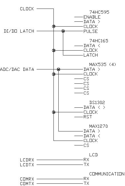
I am trying to connect a lot of different Integrated Circuits to a Javelin Stamp (it has the same # of I/O pins as the BS). I don't know if I am going to have enough pins to complete this task. I have attached a picture that shows the devices I am trying to connect, and I am looking for suggestions on how to connect all these devices. I have already shown some connections I plan on using. Is there any suggestions?

Thanks,
-Jon
437 x 651 - 30K

Comments

  • Chris SavageChris Savage Parallax Engineering Posts: 14,406
    edited 2006-11-21 20:46
    Well, it seems like you’re already sharing bus lines that can be shared.· Seems like the MAX535 is taking the most I/O…I don’t know much about that chip except it’s a DAC, but with some clever programming you may be able to control the CS lines for all those chips by adding another 74**595, which wouldn’t take any additional I/O pins to do and would free up all CS lines for said chips, as well as possibly the DS1302 and possibly the MAX1270.· I hope this helps, or at least gives you some ideas.· Take care.

    ▔▔▔▔▔▔▔▔▔▔▔▔▔▔▔▔▔▔▔▔▔▔▔▔
    Chris Savage
    Parallax Tech Support
  • GadgetmanGadgetman Posts: 2,436
    edited 2006-11-22 08:42
    I prefer a 74HC138 3-to-8 decoder chip for CS signals.

    And you can hook up the serial lines for your LCD using a 74HC245 or similar chip.
    (Also controlled by the 138 )

    ▔▔▔▔▔▔▔▔▔▔▔▔▔▔▔▔▔▔▔▔▔▔▔▔
    Don't visit my new website...
  • Jon KeinathJon Keinath Posts: 146
    edited 2006-11-23 02:49
    Thanks for the suggestions!

    I will look into implementing them, and let you know how it turns out.
  • Jon KeinathJon Keinath Posts: 146
    edited 2006-12-11 16:56
    Results...

    I was able to combine the CS Chips by adding a 74**595, but I had to separate the clock lines to the 595 and the MAX535 DAC.

    ▔▔▔▔▔▔▔▔▔▔▔▔▔▔▔▔▔▔▔▔▔▔▔▔
    -Jon
    www.jonkeinath.com
  • Dennis FerronDennis Ferron Posts: 480
    edited 2006-12-17 08:05
    On my robot motor controller I was able to add a multiplexer, to even though I didn't have any extra pins, by using one pin as both an input and an output at once. I took 4 data lines that I was using to output data to my LCD and hooked up the 3 address lines from a 74151 multiplexor to them, and also connected the 4th line of the LCD data bus to the output of the 74151, but through a 1K resistor. That way, when the Basic Stamp is driving the data lines to send data to the LCD, the 74151 is receiving random addresses and trying to output but the 1K resistor prevents too much current from flowing during this bus contention, and the LCD only sees the proper output from the Stamp. The LCD remains none the wiser that there is really a 74151 connected too. Then, when I read the 74151, I set that pin to an input and I am able to input the signal that the 74151 is sending, because the Basic Stamp doesn't load the 1K resistor too much. The LCD module sees "garbage" on its data line while I am reading the 74151, but this only occurs while the LCD's E line is disabled, so the LCD is not affected.

    I originally used a 10K resistor to protect the 74151 from having to source too much current (TTL doesn't like to source current) but found that with a 10K resistor it was not able to pull the LCD input low enough, so I changed it to 1K, which should still not cause damage to the 74151.
Sign In or Register to comment.