

Aeronautical Engineer's advice needed
 Pierson
Posts: 33
Pierson
Posts: 33
I'm trying to help out my Dad with a project he's been working on for a while. We haven't discussed·it recently, but I'd like to do something for Christmas.
He's an aero engineer, and has been building model airplanes for over 60 years. He's interested in airfoils, and to satisfy an urge, he built a NASA Baals wind tunnel. The problem is instrumentation. He wants to use electrical strains guages with an amplifier. He so far hasn't come up with an interface solution.
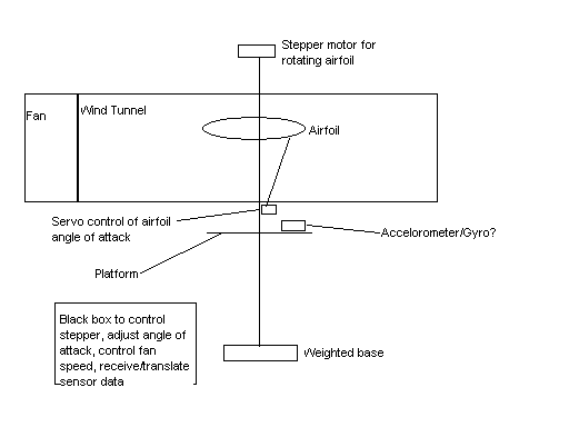
My idea is to use an H48C and a Stamp to measure forces on the airfoils that he's testing. I'm just trying to find out from you guys if I'm in the ballpark with my idea. I have a little schematic I'm trying to upload into this document that will explain it better than I can type it. I hope that it at least comes through as an attachment.
He's an aero engineer, and has been building model airplanes for over 60 years. He's interested in airfoils, and to satisfy an urge, he built a NASA Baals wind tunnel. The problem is instrumentation. He wants to use electrical strains guages with an amplifier. He so far hasn't come up with an interface solution.
My idea is to use an H48C and a Stamp to measure forces on the airfoils that he's testing. I'm just trying to find out from you guys if I'm in the ballpark with my idea. I have a little schematic I'm trying to upload into this document that will explain it better than I can type it. I hope that it at least comes through as an attachment.
Comments
To cover all that, you'd need reflective bits that are bitmapped for photogrammetry resolving about 6 degrees of freedom.
As it is, you need to measure three.
Assuming an airfoil of 0 sweep and constant chord how are you mounting it? I don't see a sting.
Post Edited (tperkins) : 11/18/2006 4:14:13 PM GMT
I have no idea what you're talking about·with reflective bits, bitmaps, photogrammetry. Help, please?
Photogrametry is where you measure the distance between known points in a photograph and compare them to unknowns to determine unknown distances. In a wind tunnel where the model is free floating, it can be used to find the forces on the model. Motion capture (without resolving the forces involved, just displacements) is what the Hollywood people call it.
Yours, TDP, ml, msl, & pfpp
I was a chapter president for the EAA (Experimental Aircraft Association). They either know how to get stuff like this set up or can point you to resources that can or will help. The EAA is specificly set up for people who want to build or work on their own airplanes and I know that the BEDE series on aerodynamics goes into that stuff. Granted the series is about a dozen tapes and costs a bit...
Anyway, the link to the EAA home page is http://eaa.org/
If you can't find what your after by browsing the website email·or call headquarters and they will do what they can to help you. Their library is rather exentsize (sp?) ·and even carried a few documents on the flying saucer that Hitler was supposed to have been working on.
You can also surf through aircraft spruce, they are a major supplier of parts to people in the EAA. The link is http://aircraftspruce.com/
Thanks for the advice. Dad has been a member of EAA and gone to Oshkosh every year for over 25 years. I believe he first saw the Baals wind tunnel at a NASA pavillion. I have done some internet research but not come up with anything helpful as far as instrumentation. The two that I remember was a graduate student who used some Lego Mindstorms parts, and her advisor asked that if I ever came up with a better solution that I send him my results. There was also a company that does aerodynamic testing on model rockets using the Baals windtunnel, but I never got a serious response from them.
I believe that what info/advice Dad got up at Oshkosh was to contact Omega.com. I'm looking at Omega's 'The Pressure Strain and Force Handbook', a sort of bible for this sort of stuff. A lot of good educational stuff, and also a catalog. But the sensors and the software are very, very expensive. I was looking for a cheaper alternative.
I'm going to ask him to bring back some pictures of Hitler's flying saucer next year.
Heres what I can pass on and this is based on a full airplane model. For only an airfoil adjust things accordingly.
Use·four tri-axis acceleramoters to measure roll, pitch, yaw and to·collect data on g's. One acceleramoter goes on each wing tip, one in the nose and one in the tail. This configuration gives more exact data because of the locations, the sensativity to·movement·and g's. Put a BS2 in the center of gravity so nothing gets affected and put in your controls for the airplane just like it were an RC airplane. In short the BS2 controls everything with nothing exposed on the outside.
Next hook in a wireless transmitter - Parallax sells ones with 500 ft ranges so they would probably be note worthy.
The BS2 transmitts data to external computer source - for recording only - while it maintains a straight and level attitude via the use of accelerometers. To change the program simply open the cover on the model, hook up your cable and download the next program.
For sensors - Parallax has several touch sensors. Mount these internally against the skin so that pressure changes can be monitored on top, bottom, and leading edges. For trailing edge use a sensor to monitor the pressure on the push rod moving the aleron. If so desired an IR can be mounted on top bottom, leading edge, trailing edge and both exterior edges of any model, this gives measurments to each of the locations within the wind tunnel and by tracking changes, you can also get things like rate of climb, accuracy of acceleramoter changes, turn and bank·etc.
All told, without the wireless the Basic Stamp can do most of this. With the wireless you get immediate data.
I think I spend to much time at the airfield...
I would personally build a seires of programs as follows:
Straight and level Flight
30 degree turn
Level to 30 degrees and back
Climb up to half of stall
Climb to stall angle
Descend to half of VNE
Descend to VNE
And, of course, combinations for the fun of it.
Yours, Tom P.
Thanks for your ideas. They show ingenuity.
Looking at the old school books is a great idea. I'm sure Dad still has his college texts.
Keep the ideas coming!
Some of the buttons on a PS2 control pad are force sensitive. I have no idea how they work or what kind of resolution you can get from them.