

12Volt Circuit revise to 6 Volts Can it be done?
 metron9
Posts: 1,100
metron9
Posts: 1,100
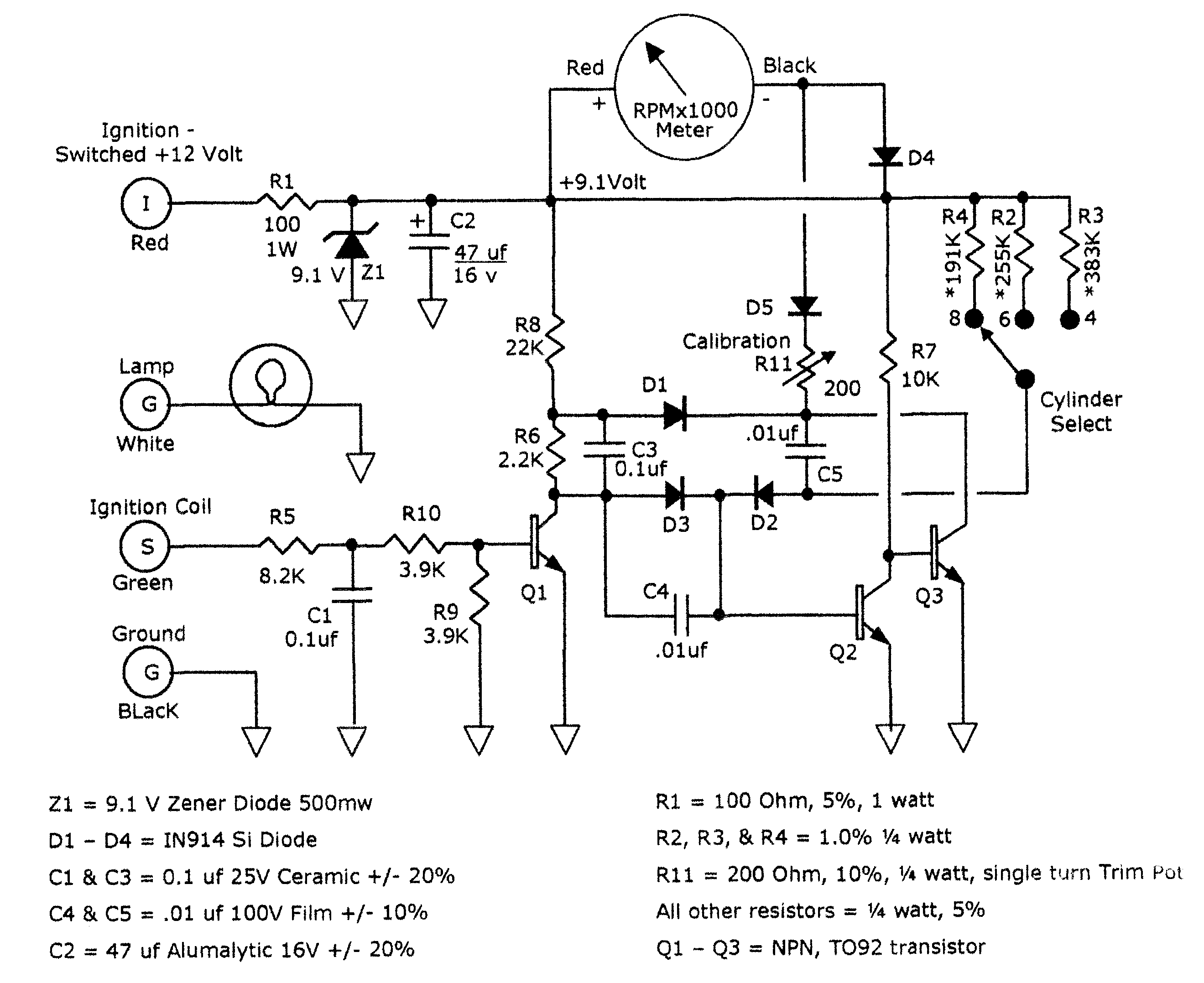
I have a friend that repairs guages. He uses a circuit board (attached schematic) to drive the Tach. The problem is, he wants to use these boards in a 6V battery operated car (old cars)
The solution he has now is to use a DC-DC converter to increase the voltage to 12V
http://www.v-infinity.com/pdffiles/PK1.5_D5-S12.pdf
The above part is 11.83 each in 100 min qty. He will be using 500 per year or so.
Can this circuit be redesigned to make it much smaller, run on 6V without the above solution.
I see it really only uses 9.1V as the zener regulates the 12 to 9.1
He would like to buy the circuit boards and solder the parts in house.
any other information you need I can get.
▔▔▔▔▔▔▔▔▔▔▔▔▔▔▔▔▔▔▔▔▔▔▔▔
Think Inside the box first and if that doesn't work..
Think outside the BOX!
2639 x 2155 - 133K
Comments
I'll ask around
I'm just going to give it a go and redesign it with a tiny13 and fast pwm for a simple $3.00 dollar board that will run 6 or 12v systems and junk the board that comes with the gauge. That's my solution unless it gets shot down for some reason.
▔▔▔▔▔▔▔▔▔▔▔▔▔▔▔▔▔▔▔▔▔▔▔▔
Think Inside the box first and if that doesn't work..
Think outside the BOX!
much lower supply voltage.Makes it appear that just because of that.the solution is to run it with the dc/dc converter to up the supply to the meter's design range.But also the pulses being read from the coil will be out of range at 6 volts versus 12 which might be corrected by changing R5,R9.andR10.
LOL . Jim Richey
▔▔▔▔▔▔▔▔▔▔▔▔▔▔▔▔▔▔▔▔▔▔▔▔
Thanks, Parallax!
I just don't have a clue yet how this circuit works, I imagine it is similar to PWM in that the pulses that come in translate to a current to drive the meter There are too many components to put it in the java circuit simulator, I wish there was a larger version of that where it shows the current flowing through the parts.
Added some more information I got on the gauge
▔▔▔▔▔▔▔▔▔▔▔▔▔▔▔▔▔▔▔▔▔▔▔▔
Think Inside the box first and if that doesn't work..
Think outside the BOX!
Post Edited (metron9) : 11/15/2006 4:29:24 AM GMT
Rather than trying to modify it's operation,it might be more feasable to work out your own version of a frequency to voltage converter to power the existing meter It wouldn't hurt to "modernize" it with solid state components .Let us know how it works out,I'm curious.
Jim Richey
▔▔▔▔▔▔▔▔▔▔▔▔▔▔▔▔▔▔▔▔▔▔▔▔
Thanks, Parallax!
I would be open to ideas on protection for the input of the tachometer line since I don't have any specs on it. Testing his MSD output tach output, something one of his other guys rigged up that has a auto coil and simulates 4,6 and 8 cylinder output measures 3.5 V average voltage on its output but I don't know how much noise it has. I am just going to set a demo up and let it run on that device to see what I get. tinys are less than a buck and I have quite a few of them. I hthink I can just use its internal oscillator as the average error will not effect the gauge output by more than the variable frequency going in at any moment under driving conditions. I plan to average the input frequency and move the meter gradually twards the position it should be.
I am glad you think its beyond human comprehension, as i cant make any sense of it at all. If I lump it to a simple input output black box, I think it just works like a PWM and a simple circuit to do that seems like a simple task. I may play with that idea if I run into trouble with any of the frequency counting aspects of the microprocessor design.
The chart for RPM, 4,6 and 8 cylinder is attached, change the extension to XLS and load in excell
▔▔▔▔▔▔▔▔▔▔▔▔▔▔▔▔▔▔▔▔▔▔▔▔
Think Inside the box first and if that doesn't work..
Think outside the BOX!
Post Edited (metron9) : 11/15/2006 6:05:01 PM GMT
Jeff T.