

Digital Pot Transistor Range Scaling
 metron9
Posts: 1,100
metron9
Posts: 1,100
I am working with andy on his laser project. Since I am not so good with analog circuits I pose this question.
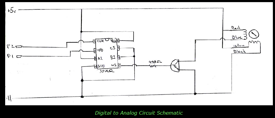
The circuit attached uses a 10k 100 step digital pot. The current to one of the windings on a stepper motor is being varied to move a mirror very slightly. We have found through trial and error that the motor only moves from 13 to 20, or 1300 ohms to 2000 ohms. I don't know the exact transistor he is using but from the experiment we know the transistor must be in saturation at 1300 ohms and below and fully off at 2000 ohms or greater. This gives a step range of only 7 positions.
How can we get more resolution from the pot to control the transistor more precisely in its linear range?
Basically from 100 ohms to 10,000 ohms we need to convert or scale it to 1300 ohms to 2000 ohms giving us 700 ohms / 100 or 7 ohms per step instead of 100 ohms per step.
I don't know the voltage or current rating on the motor either.
▔▔▔▔▔▔▔▔▔▔▔▔▔▔▔▔▔▔▔▔▔▔▔▔
Think Inside the box first and if that doesn't work..
Think outside the BOX!
Post Edited (metron9) : 11/13/2006 4:41:38 PM GMT
906 x 390 - 101K
Comments
Thank's
▔▔▔▔▔▔▔▔▔▔▔▔▔▔▔▔▔▔▔▔▔▔▔▔
Think outside the BOX!
▔▔▔▔▔▔▔▔▔▔▔▔▔▔▔▔▔▔▔▔▔▔▔▔
www.laser-man.co.uk
I rigged it up and tested it with an LED.
The thing we don't have is the motor current requirement. The current to the transistor base is based on the current flowing thru the transistor to lock in on its linear range.
I used a regular 10k pot instead of a digital one to test the circuit
Turning the 10k pot up full where the led was brightest (most current) I turned the trimpot until the brightness just dimmed a little. Then using the 10k pot I could adjust the brightness of the LED from off to just barely lit to full on across the range of the 10k pot.
The motor andy is using will have to use the same thing I think to adjust or trim the input current to the base of the transistor. I do it by trial and error because that's the only way I know to do it.
I would replace the LED with the motor winding wire
I would set the trimpot to full on (0 ohms between wiper and input from 10kpot
I would then turn the 10k pot to full one way or the other and leave it at the side the motor was moved the most.
Then I would adjust the trimpot till the motor just moved back a tiny bit.
This should then allow you to move the motor smoothly with the 10k pot from its full left position to its full right position where ever those two points would be. I still dont have a clue as to how far the motors actually move but I would think it would be 1/2 of the 36 degrees or somewhere around 15 degrees.
Attached LED pictures of circuit on breadboard.
I actually have some steppers so I think I will puts with this, the ones I have have I think are 7.2 degree steps but I will have to look at the datasheets.
Please correct my assumptions above, I usually find my own mistakes but only after I actually build something and this is just a part of something.
▔▔▔▔▔▔▔▔▔▔▔▔▔▔▔▔▔▔▔▔▔▔▔▔
Think outside the BOX!
Post Edited (metron9) : 11/12/2006 9:11:33 PM GMT
PJ Allen's schematic was suppose to be used in place of the digital pot --- not in addition.
An LED is certainly not equal to a motor in current consumption. I wonder if you are getting any useful info from such.
Actually, having a digital potentiometer control an amplifier gain [noparse][[/noparse]whether transistor or op amp] is a very useful idea.
I have been looking at digital pots and wonder how to really make use of them. The often need the boost of a power amplifier.
I suspect that the original circuit is just fine as transistors have a wide range of gain and one will work from 1300 to 2000 while another will work in a different range.· You are going to have to test and calibrate whatever you build in this setup.
▔▔▔▔▔▔▔▔▔▔▔▔▔▔▔▔▔▔▔▔▔▔▔▔
"If you want more fiber, eat the package.· Not enough?· Eat the manual."········
Post Edited (Kramer) : 11/13/2006 8:54:50 AM GMT
(if could be as simple as two coils and a moving arm suspended between them, or it could be a complete motor with blocks to stop it from rotating too far)
They're using the difference in two magnetic fields to quickly and (hopefully) accurately move the motor. Increase the strength of one field to move the rotor towards the coil, and decrease the field to move it the other way.
In theory, it should be possible to do it with normal steppers, too, but I've never tried.
(another item on the long, long list of things to mess with... )
Edit: You may want to use a slightly smaller than 1K Omh resistor parallell with the digital pot if you want to improve the accuracy more. At the full 10K setting they will result in about 900 Ohms, and a total with the 1.3K you end up with 2.2K
(you wrote that it was fully off at 2K, so the 'extra' .2K is wasted.)
The formula is something like:
1/TotalOhm = 1/PotOhm + 1/ParallelOhm
which should end up at about 750 Ohms to get the full 700Ohm range.
(This all depends on which resistors you use, of course, as I doubt 1.3K and 750 Ohm resistors are very common... )
▔▔▔▔▔▔▔▔▔▔▔▔▔▔▔▔▔▔▔▔▔▔▔▔
Don't visit my new website...
Post Edited (Gadgetman) : 11/13/2006 10:47:15 AM GMT
· It's all this "out of the box" stuff.· I just don't get it.
· ** Post Edit **· At any rate, you're not varying the current at all, given that common-emitter circuit, I guess, is being shown.· It's just switching --·as the emitter, presumably, is at GND; it's not current-sourcing at all.
Post Edited (PJ Allen) : 11/13/2006 11:54:26 AM GMT
http://cgi.ebay.com/ws/eBayISAPI.dll?ViewItem&item=7555895146&rd=1&sspagename=STRK:MEWN:IT&rd=1
▔▔▔▔▔▔▔▔▔▔▔▔▔▔▔▔▔▔▔▔▔▔▔▔
www.laser-man.co.uk
▔▔▔▔▔▔▔▔▔▔▔▔▔▔▔▔▔▔▔▔▔▔▔▔
(Frequently heard from other's)
Tommy, I know it wasn't designed to·x, but can you make it·do x·anyway?
·
First, The design for the laser mirrors using a stepper motor and one winding to microstep or move it smoothly in a narrow range is not my idea. This outside of the box thinking belongs to Boomdog, the original designer. Andy asked for help in another thread, I have been working with him on the basic stamp code that runs this device. I ren into trouble assuming the stepper motors were being controlled by a "normal" stepper board and that the puls output simply moved the stepper one step forward of backwards. That is not the case. It turns out that the pulseout code is incrementing or decrementing a digital 10k pot to vary the current to one of the windings on the mirror. (There are two 10k pots and two motors that make up the mirror arrangement)
We have been working thru the Private Message channel for a few days as I try to get a handle on just what the hardware is doing. I'm surly not trying to think out of the box here as I am dealing with a black box and trying to figure out what is in it.
I don't know the specs on the motors, voltage or current.
I don't know what transistor he is using.
The device works to a point, it displays a wobbly square on the wall and various other patterns. I originally told Andy, we need to find a zero point or a calibration point of the mirrors so we can understand how far the mirror travels in the 100 step range. This has been a challange as Andy is totally new to code and understands very little about what it is doing. The feedback I am getting from Andy is getting better as he learns to spot errors in the code and make some changes.
Where are we now?
We were able to figure out the Y direction mirror moves between 1300 ohms and 2000 ohms or there abouts. So I made some code to step it in one second intervals so andy sould see what the code was doing. The Y direction works and we see 7 steps one direction and back the other direction. The X direction is not working, I dont know if it's the hardware connection or the code yet but I decided to eliminate that variable and focus on just the Y mirror since we had it working. I assumed Andy did not have a smaller digital pot with finer resolution and that was the reason for this post. I knew there was a way to scale the output of a pot so I asked how to do it.
The Problem of course is I did not understand where the 100 ohm resistor on the top of Pj's schematic was going. So Instead of asking I simply dove in to figure it out. How do I connect it? Well it turns out the connection I made works, the 100 ohm resistor is tied to ground, +5V is input at the 1300 ohm resistor and the variable current is output at the wiper. Now to test this I used a meter and looked at the current to the base and that was all well and good. So I needed a load through the transistor, as I stated I understand the linear range of a transistor the point between fully off and fully on, and I understand it to be dependent on the load through the transistor, thus not knowing the load specs of the motor winding I replaced the fixed 470ohm resistor in the original schematic with a 5K pot I had laying around. I drew the schematic the way I thought pj ment to implement it not something I wanted to be outside the box, I then asked if what I did was correct.
I shal try and answer the questions and assumptions put forth so we can all be on the same page.
I hope the above answers your first statement. I am not sure what you mean by "in place of the digital pot" as we were modifying the digital pot to scale its output not replace it.
I many times use an led instead of a meter to test aspects of a circuit, Thats why I added the trimpot to dial in the output current range of the digital pot for an unknown load.
Your point 3 is well taken, Small signal analysis uses the linear range of a mosfet to amplify a signal using a bias voltage so the signal rides on the bias. This is similar in what this circuit is doing and I am trying to find the window of the range via email with someone who has very little experience in measuring voltage or current levels.
Gadgetman, you are correct, in your statement "They're using the difference in magnetic fields..." I actually tried it on a 7.5 degree step motor and it works, a variable precise movement between the 7.5 degree step. Like I stated before it is from the looks of it perhaps 50% of the full step that you can control. I also have a theory that it is not linear to the amount of current in at one end vs. the other end but this aspect I have not put on the table. Perhaps Kramer can do s spice model to see the curve?
Without knowing the motor specs it is hard to nail down the range for the current to the base of the transistor.
Pj, you are throwing your hands up because you think I want to be outside the box. Truly I don't, as I explained above I did not know how to connect your circuit to modify the original schematic, so I did what I thought was right and tested it, it works as it varies the current and resistance in the range specified so I am still unclear what I did that was so out of the box. Please submit a complete schematic integrated to the original schematic so I can understand what you mean.
Your edit, seems to be not the case as the LED and meter clearly show the current is variable between the two points. It is very possible I messed up the schematic and it is not what I have on the proto board and that of course is what my original statement at the bottom of the post was for.
To sum up , we all assume things that drive our thinking one way or the other let me be clear. I very much appreciate all the help from everyone here, I am only trying to follow your suggestions, I make mistakes and do it wrong sometimes and that's why I ask for additional help.
So Please, if you have time, whip up a schematic the way you intended it to be implemented the full concept of this device is very simple when you boil it down, getting to the right current levels for the base voltage on the transistor with enough granularity to move a laser mirror smoothly back and forth is the goal here, actually this post was about the scaling of a pot but I think that in itself is a good thing to know about.
Tommy Bot
I am sure if you read this post your questions are answered.
Andy, perhaps you could put a link to the last test we did stepping the laser. This test was to move the x axes 7 steps left, the y axes 7 steps up, the x axes 7 steps right, and the final move y axes 7 steps down to make a square. As I said for some reason the Y axes was not working, but the X did what the code told it to do and that was at least a tiny success.
▔▔▔▔▔▔▔▔▔▔▔▔▔▔▔▔▔▔▔▔▔▔▔▔
Think Inside the box first and if that doesn't work..
Think outside the BOX!
Post Edited (metron9) : 11/13/2006 3:39:40 PM GMT
http://www.galvos.com/index.php?cls=online&id=17277&wysiwyg=true
Link on home built laser device
http://elm-chan.org/works/vlp/report_e.html
▔▔▔▔▔▔▔▔▔▔▔▔▔▔▔▔▔▔▔▔▔▔▔▔
Think Inside the box first and if that doesn't work..
Think outside the BOX!
here is our last test -
ok x movement is going fine, but the y movement is not working at all as u can see from this vid. As soon as the dot starts moving left, is when i loaded the code in.
http://s80.photobucket.com/albums/j185/andy_con/?action=view
http://i80.photobucket.com/albums/j185/andy_con/DSCN3065.jpg
http://i80.photobucket.com/albums/j185/andy_con/DSCN3066.jpg
▔▔▔▔▔▔▔▔▔▔▔▔▔▔▔▔▔▔▔▔▔▔▔▔
www.laser-man.co.uk
Maybe my language I use when discussing current and voltage is not correct but I looked it up again and well maybe this is wrong too.
"
The BJT is commonly described as a current-operated device because the collector/emitter current is controlled by the current flowing between base and emitter terminals. Unlike the FET, the BJT is a low input-impedance device. As the base/emitter voltage (Vbe) is increased the base/emitter current and hence the collector/emitter current (Ice) increase exponentially (Ice ∝ KVbe where K is a constant). Because of this exponential relationship the BJT has a higher transconductance than the FET.
"
▔▔▔▔▔▔▔▔▔▔▔▔▔▔▔▔▔▔▔▔▔▔▔▔
Think Inside the box first and if that doesn't work..
Think outside the BOX!
Ive just brought a new laser module for my scanner, so next week when it arrives i have to take everything out of my scanner. So i will check all connection and double check its wired up correct.
those two pics i just posted, was the information that came with the galvos.
▔▔▔▔▔▔▔▔▔▔▔▔▔▔▔▔▔▔▔▔▔▔▔▔
www.laser-man.co.uk
Again, this is not my "contraption" although I am sort of a rube goldberg kind of guy It is this web site that has the information andy is using as a laser controller device.
http://lasers.musicfoxaudio.com/byoshow.htm
Just under the galvos picture you will note
Referring to the schematic you posted.
So , I will en devour to build a circuit that operates like the circuit this Boomdog is not using (the one you refer too) although my initial intention was not to get into the hardware aspects of this project with andy I'm too deep in it now not to finish it. I guess that schematic will have to suffice as the spec sheet for the galvos.
That's why I like this board, the views presented here are usually outside my box of thinking as a matter of fact that idea alone is more than likely the solution to the problem. I should have guessed looking at the sloppy code the hardware design would be just as sloppy but like I have said before, hardware schematics are still pretty hard for me to understand, I still don't have a handle on "node method" so a circuit analyst I am not.
Thanks pj
▔▔▔▔▔▔▔▔▔▔▔▔▔▔▔▔▔▔▔▔▔▔▔▔
Think Inside the box first and if that doesn't work..
Think outside the BOX!
when i first started the project i put the transistors the wrong way round and it didnt work. So when i realised i change them the right way round, could this have affected the transistors????????
▔▔▔▔▔▔▔▔▔▔▔▔▔▔▔▔▔▔▔▔▔▔▔▔
www.laser-man.co.uk
Another thought, as this may have been suggested above, is to take a variable DC power supply or pot in series with a voltage and slowly adjust the voltage to see what the motor does out of the circuit.
Put a thin piece of tape as a reference and come up with a list of positions
e.g.
1V = 10 Degrees
2V = 20 Degrees
etc.
Then you can use dip switches or the micro stepping through the pot and use a voltmeter to measure the output of the digital pots.
·Once we got that, then we need a driver for the circuit, and we can look into the transistor.
Also it's looking like the galvo goes up to 14V, but reading some of the details mentions 5V, so let's keep it there and see if it's linear.
Post Edited (Yendor) : 11/15/2006 3:56:03 AM GMT
Metron is a coding god!!
▔▔▔▔▔▔▔▔▔▔▔▔▔▔▔▔▔▔▔▔▔▔▔▔
www.laser-man.co.uk