

Building My Own Motherboard: Serial setup, Caps Etc.
 Zoot
Posts: 2,227
Zoot
Posts: 2,227
I'm building my own small motherboard for my 'bot and BS2p40 so I can reclaim my demo board which is currently bolted into the guts of the 'bot.
I really want to use a 4 pin header for my serial connection and then use a PropPlug. The PropPlug documentation says it may be used for Stamps as well, and getting double duty out of the device would be great.
Questions:
- is that correct that I can use the PropPlug to program a Stamp?
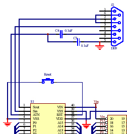
- see below attachment of serial setup to Stamp. If I build 4 pin header connections to match the PropPlug, can I -- should I -- eliminate the caps on the Serial lines? I would think these apply only to true serial connection, not to USB -> PropPlug
- can I also not worry about loopback connections and the like on what would be non-existent serial port?
- if I didn't want to use PropPlug, could I wire my own serial cable terminating in 4 pin plug? But if I did, then I would think I would need proper loopback connections and caps on the custom-wired cable (I may do this while I wait on arrival of new PC notebook -- current PC has serial ports).
▔▔▔▔▔▔▔▔▔▔▔▔▔▔▔▔▔▔▔▔▔▔▔▔
When the going gets weird, the weird turn pro. -- HST
Post Edited (Zoot) : 1/10/2007 5:50:29 PM GMT
I really want to use a 4 pin header for my serial connection and then use a PropPlug. The PropPlug documentation says it may be used for Stamps as well, and getting double duty out of the device would be great.
Questions:
- is that correct that I can use the PropPlug to program a Stamp?
- see below attachment of serial setup to Stamp. If I build 4 pin header connections to match the PropPlug, can I -- should I -- eliminate the caps on the Serial lines? I would think these apply only to true serial connection, not to USB -> PropPlug
- can I also not worry about loopback connections and the like on what would be non-existent serial port?
- if I didn't want to use PropPlug, could I wire my own serial cable terminating in 4 pin plug? But if I did, then I would think I would need proper loopback connections and caps on the custom-wired cable (I may do this while I wait on arrival of new PC notebook -- current PC has serial ports).
▔▔▔▔▔▔▔▔▔▔▔▔▔▔▔▔▔▔▔▔▔▔▔▔
When the going gets weird, the weird turn pro. -- HST
Post Edited (Zoot) : 1/10/2007 5:50:29 PM GMT
252 x 266 - 47K
Comments
·
·· You cannot use the PropPlug to program the BASIC Stamp.· The BASIC Stamp is expecting an inverted RS-232 signal at its programming port.· But the output of the PropPlug is non-inverted TTL level.· You can use it for communication on the I/O lines, but not for programming a module.· Now, if you have an OEM setup, you could use it by using the first schematic at the following link.· It says USB2SER, but either will work.· Again, this is for an OEM Stamp Module without the RS-232 interface circuitry which consists of 3 transistors and bunch of 10K resistors.· Take care.
http://forums.parallax.com/showthread.php?p=567989
▔▔▔▔▔▔▔▔▔▔▔▔▔▔▔▔▔▔▔▔▔▔▔▔
Chris Savage
Parallax Tech Support
Drat. I thought it sounded too easy -- I didn't read the description of the PropPlug closely enough... it says "communication with a Basic Stamp" not programming.
That said, if I wanted to use a 4 pin header with a small connector plug instead of a DB serial connecter, could I still wire up my own DB to 4pin cable. I like the compactness of having a header for connecting rather than big ol' DB plug? I also have plenty of those lying around.
▔▔▔▔▔▔▔▔▔▔▔▔▔▔▔▔▔▔▔▔▔▔▔▔
When the going gets weird, the weird turn pro. -- HST
·
·· There is no doubt it’s great for simple communication with a PC because you don’t need RS-232 conversion…And, as I said, the bonus comes for those who built the BS2 into their design without the transistor circuitry.· Those units can be programmed.· Take care.
▔▔▔▔▔▔▔▔▔▔▔▔▔▔▔▔▔▔▔▔▔▔▔▔
Chris Savage
Parallax Tech Support
▔▔▔▔▔▔▔▔▔▔▔▔▔▔▔▔▔▔▔▔▔▔▔▔
When the going gets weird, the weird turn pro. -- HST
- I've got the BS2p40/24 demo board bolted in as the motherboard for my 'bot. I'm replacing it with my own prototype board with a socketed BS2p40 and all the other stuff that I've got breadboarded currently.
- I would think I'd need to duplicate the Serial socket to Stamp portion of the circuit above from the demo board.
- then I thought that rather than running wires out to a DB-9 socket for programming the Stamp via serial, I wanted to use a 4-pin header instead, partly for aesthetic/space reasons, partly because I thought I might be able to use a PropPlug for programming (I can't since I'm not using an OEM stamp and don't plan to for this project -- but it's such a great idea)
- then I'd need to make up my own cable with DB-9 on one end and 4pin header plug on the other (to plug into a USB2SER or a regular Serial cable) for programming.
- so then I thought that I would eliminate parts of the circuit above (the loopback connection on the Serial DB-9 and the two caps) and just wire the loopback and the caps directly into my custom cable.
Does that make sense?
I guess the whole thing begins to sound a bit kludgy, and I would only be able to program with my custom cable. Maybe I'll just find room for the DB-9 socket which would certainly be simpler and easier
Below is full schematic of my version of the demo board. AllanLane5 -- it sounds like you are saying there is possibly an error in the schematic from Parallax? I can't pull the board right now and actually look at the traces. It's funny you bring that up because there is a cap physically on the demo board that is *unaccounted* for in the schematic; I just haven't had a chance to pull the board and see what it's connected to. The schematic and the board have the two 47uf caps for the regulator and the two tantalums on the Serial port, but there is a fifth tantalum cap on the board itself (it's about halfway down the board; seems unelated to the serial port or power supply).
▔▔▔▔▔▔▔▔▔▔▔▔▔▔▔▔▔▔▔▔▔▔▔▔
When the going gets weird, the weird turn pro. -- HST
Post Edited (Zoot) : 11/12/2006 3:53:31 AM GMT
Thus your adapter would be: Pin 6 tied to pin 7, and wires for TX, RX, DTR, and Ground.· With two capacitors -- one in-line with DTR, and one between DTR and Ground.· You COULD do without these capacitors IF you use the BS2 IDE.· These two capacitors 'decouple' the DTR signal from holding the BS2 in reset.· The BS2 IDE 'knows' about this, and only 'pulses' the DTR line to reset the BS2.· Hyperterm, on the other hand, is very stupid about this signal, and without the two capacitors will hold the BS2 in reset.
Personally, I don't think it sounds too kludgy -- instead you get your BS2 with a cute little 4-pin header next to it on your board. Plug in your simple adapter to program.· Kind of clever, really.
Post Edited (allanlane5) : 11/12/2006 11:55:44 PM GMT
Yes, I'm always programming from the Pbasic IDE, not hyperterminal. And now I realize what you meant -- there are really six wires being used in a regular Stamp/Serial connection -- two for the loopback, 4 for GND, SIN, SOUT, ATN.
Got it. Thanks to all for your help. Esp. thanks for explaining the purpose of the caps on the ATN line.
▔▔▔▔▔▔▔▔▔▔▔▔▔▔▔▔▔▔▔▔▔▔▔▔
When the going gets weird, the weird turn pro. -- HST
- I realized that the Basic Stamp manual schematic for wiring the serial port to a BS2p40 specs .1uf 100 V caps. I only have .1uf 50 V caps here. Can I get by with those? I have decided to wire the caps into the port and not into the cable, btw.
- I'm using the AIN pin of an Emic for FREQOUTs (so that sounds from the Stamp can be amplified by the Emic's onboard amp). Is it generally better practice to keep analog audio and such off my motherboard? In other words, there's simple circuit with caps, resistors and a pot for conditioning the FREQOUT signal before amplification. Since the Emic is located a decent distance from my motherboard, am I better off running my digital FREQOUT wire to the filter circuit (about 6" say), rather than putting the filter circuit on the mother board and running a long analog wire to the Emic?
Thanks to all for their help on this.
▔▔▔▔▔▔▔▔▔▔▔▔▔▔▔▔▔▔▔▔▔▔▔▔
When the going gets weird, the weird turn pro. -- HST
As for the caps…Typically you should spec capacitors for twice the expected maximum voltage in the circuit. So anything above that voltage would work for these type of caps (bypass). Short answer is yes, the 50V caps will work. Take care.
▔▔▔▔▔▔▔▔▔▔▔▔▔▔▔▔▔▔▔▔▔▔▔▔
Chris Savage
Parallax Tech Support
2. Digital circuits tend to be 'noisy' in audio frequencies. So yes, you should
put the audio filter close to the Emic.
Two unrelated questions:
1. My BS2p40 was shipped already inserted into my demo board, where it's been in use for about a year. How can I extract the Stamp without breaking it? Popsicle stick? I don't have an IC extractor that big.
2. I'm wiring up my own serial to four-pin header programming cable. Is the schematic for wiring to the serial port in the Stamp manual for a MALE plug, or is it showing a FEMALE plug from the solder side? Look at the two images below and you'll see what I mean. I'm wiring to a male DB9 and will be plugging that into a regular serial cable. I was just going to wire following the DB9-general pinout since it's labeled
▔▔▔▔▔▔▔▔▔▔▔▔▔▔▔▔▔▔▔▔▔▔▔▔
When the going gets weird, the weird turn pro. -- HST
This is because the BOE expects to be connected to the 'male' (with pins) DB-9, RS-232 connector on the PC with a straight-through Male to Female wired RS-232 cable.
The picture you have is correct if you have a male (with pins) DB-9 connector, and are looking in at the pins. A female (with sockets) DB-9 would have its 'pin 1' on the bottom of the picture (so that they mate 1 to 1, 2 to 2, etc).
I believe the schematic in the BOE manual is showing the 'back' end of a female DB-9 connector -- the 'inside' part, where the solder cups would be. That would make the pin-outs look exactly like a male connector, seen from the pin side.
I KNOW the connector on the BOE is female (with sockets), and I KNOW the connector on the PC has pins, and it's fairly easy to find a Male to Female DB-9 cable with all pins wired straight through. I'd recommend you use a female DB-9 connector for your DB-9 to 4-pin adapter.
▔▔▔▔▔▔▔▔▔▔▔▔▔▔▔▔▔▔▔▔▔▔▔▔
When the going gets weird, the weird turn pro. -- HST
▔▔▔▔▔▔▔▔▔▔▔▔▔▔▔▔▔▔▔▔▔▔▔▔
When the going gets weird, the weird turn pro. -- HST
Thanks again to all. It's coming together nicely.
▔▔▔▔▔▔▔▔▔▔▔▔▔▔▔▔▔▔▔▔▔▔▔▔
When the going gets weird, the weird turn pro. -- HST
-Phil
Post Edited (Phil Pilgrim (PhiPi)) : 1/17/2007 11:52:37 PM GMT
Well, like I wrote above, I popped it out -- lifting pretty hard with the extractor
In any case, I made up a cable and my PC downloads to the Stamp just fine. Attached below is a photo of the soldered board (with just IC sockets, power supply, programming/reset interface) that I just tested. Also attached is a photo of my working layout, sans trimmed wires and such.
Thanks to everyone for their help, esp. on something that must seem simple to many. I don't know that I've ever had so much fun.
When I get all the new sensors, LED display and the new moboard into my 'bot I'll be sure to post info in the Completed Projects forums.
▔▔▔▔▔▔▔▔▔▔▔▔▔▔▔▔▔▔▔▔▔▔▔▔
When the going gets weird, the weird turn pro. -- HST
if I may ask what does the underside of that pref board look like and where did you got it.
▔▔▔▔▔▔▔▔▔▔▔▔▔▔▔▔▔▔▔▔▔▔▔▔
When the going gets weird, the weird turn pro. -- HST
Here's a pic of the assembled board, with and without labels. I tested it out last night and everything works perfectly.
It's OK for my first real layout and design. Like I mentioned above, once I have this installed into my 'bot along with all the new bells and whistles, I'll post full photos/video/code/info at the completed projects forum.
Thanks again for everyone's help -- I couldn't have done it alone.
▔▔▔▔▔▔▔▔▔▔▔▔▔▔▔▔▔▔▔▔▔▔▔▔
When the going gets weird, the weird turn pro. -- HST
Post Edited (Zoot) : 1/22/2007 2:58:42 AM GMT