

Water/Electrolyte level sensor
 bailout
Posts: 4
bailout
Posts: 4
Hey all, this is my first post here, however I've been playing with stamps since before the BS2 ") . Heres the question:
. Heres the question:
I have a solution of water and electrolyte (NaOH if you care) charged with 12 volts (its an electrolyzer for hydrogen). I want to detect the water level in one of the cells with screws through PVC pipe
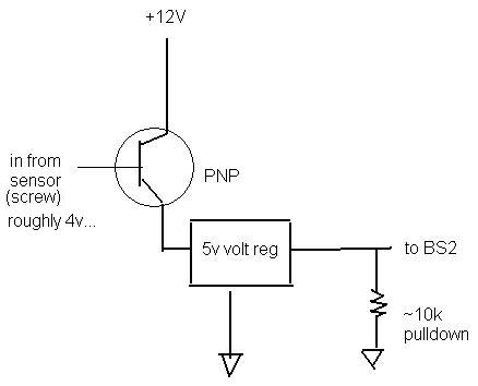
Heres what i've thought up.... (attached)
Am I in the right direction? Should there be more resistors in there or something, perhaps a diode on the screw. (i'm from the school of... what the heck do resistors do?) haha. Yea, I'm still learning
My main concern is not to burn up my stamp
I have a solution of water and electrolyte (NaOH if you care) charged with 12 volts (its an electrolyzer for hydrogen). I want to detect the water level in one of the cells with screws through PVC pipe
Heres what i've thought up.... (attached)
Am I in the right direction? Should there be more resistors in there or something, perhaps a diode on the screw. (i'm from the school of... what the heck do resistors do?) haha. Yea, I'm still learning
My main concern is not to burn up my stamp
438 x 354 - 12K
68 x 133 - 2K
Comments
1. In contact with the solution
a. a float switch
b. a conductive sensor
2. Not in contact with the solution
a. ultrasonic distance
b. IR distance
I am sure we can come up with many more ways to do this, but it really all comes back to what purpose the informaton needs to serve, how dangerous is contact with the solution, and what physical limitations exist.
In regards to your design, I wonder why you bother with +12volts and a +5 volt regulator when you already have +5 regulated available on your BasicStamp.
I also wonder why you would get the physical level of the fluid involved with its electrical activity. That makes things more complex as I guess the 4volt potential might change and provide false information.
In other words, I would go with a float device and mechanical switches if at all possible. Electrical isolation and hazard isolation are both useful. Consider a small capsule that floats a top the liquid. Have it attached to a rod on its top-side. Have the rod pass through the top of the liquid's housing. And have it directly or by lever arm, throw a micro-switch.
▔▔▔▔▔▔▔▔▔▔▔▔▔▔▔▔▔▔▔▔▔▔▔▔
"If you want more fiber, eat the package.· Not enough?· Eat the manual."········
▔▔▔▔▔▔▔▔▔▔▔▔▔▔▔▔▔▔▔▔▔▔▔▔
Shawn Lowe
My last words shall be - "NOT YET!!!"
Thanks all,
Jason
PS... if you're interested, heres some uhh "test" videos
http://www.youtube.com/watch?v=8EFFjNS0i2A· Round 1
http://www.youtube.com/watch?v=FkwLLbshUlg· Round 2
Yes, we're a bunch of rednecks
You could use a pressure transducer with setpoint contacts or an A/D converter.
What is the cell material?
If it is some type of plastic, you can use an external capacitance type sensor as a digital input to the Stamp.
Or you can use one of the various types of trip beams, multiple sensors, multiple setpoints.
Are you only concerned with low level, or constant monitoring of level?
You can put your fuel cell on a load cell and use weight and an A/D converter
Is the casing opaque or translucient?
There are many ways to skin the cat...
Float switches are available fairly cheap that are encapsulated, the reed switch is sealed in the float and the wires are encased inside the tube which is has a threaded coupling for pass through of the lid.
More details, more options
Tommy
▔▔▔▔▔▔▔▔▔▔▔▔▔▔▔▔▔▔▔▔▔▔▔▔
(Frequently heard from other's)
Tommy, I know it wasn't designed to·x, but can you make it·do x·anyway?
Post Edited (Tommy Bot) : 11/9/2006 8:18:07 PM GMT
200psi in PVC? what schedule, and size?
How is liquid expended used up, how is it replaced? Maanually or automatically?
Is there pressure relief?
▔▔▔▔▔▔▔▔▔▔▔▔▔▔▔▔▔▔▔▔▔▔▔▔
(Frequently heard from other's)
Tommy, I know it wasn't designed to·x, but can you make it·do x·anyway?
·
1st, yes 200psi in sch 40? 4" pvc (its rated for 200, i've had it to 250 (oops)
The water level is controlled by how much hydrogen is in the tank. When the tank gets full of H it will push the water down and i need it to shut off the electrolyzer (and/or open a relief valve). When the H gets low (water level high) I'll allow the solenoids to open and the H to go to the engine. Simple as that.
""Use your 4+ volts from the screw to hold down (for fail safe) (or make, if not an issue ) a solid state relay, use the dry contacts for your Stamp. Feed VSS to the hinge side of the contact, and N/O or N/C to the Stamp input.""
Thats what the transistor is for... I could be wrong, but wouldnt that have the same effect? The reason for the +12 is in case the voltage going to the gate is low (say 1-3 volts) I still need this thing to work. I figure with the right transistor, even with that 1-3 volts, it will 'open' the gate to let 3-5 volts through to make the BS2 read HIGH. Perhaps even another transistor on the other side of that regulator, switching the VSS like you were saying. Again... i do need this to work on a very low voltage, just incase.
▔▔▔▔▔▔▔▔▔▔▔▔▔▔▔▔▔▔▔▔▔▔▔▔
(Frequently heard from other's)
Tommy, I know it wasn't designed to·x, but can you make it·do x·anyway?
·