

Bridge Rectifier
 Lightfoot
Posts: 228
Lightfoot
Posts: 228
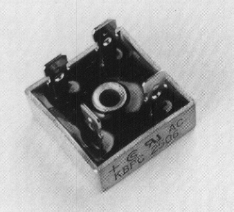
What is the proper way mount these types of rectifier (see picture) and carry the power to a printed circuit board? The circuit that will contain this rectifier will carry 10 amps at full load.
▔▔▔▔▔▔▔▔▔▔▔▔▔▔▔▔▔▔▔▔▔▔▔▔
Well well, I'm seeing things, three of them.
-Stanley Blystone
▔▔▔▔▔▔▔▔▔▔▔▔▔▔▔▔▔▔▔▔▔▔▔▔
Well well, I'm seeing things, three of them.
-Stanley Blystone
bmp
304K
Comments
If those male tabs are a standard size (say .250) female P.C. tabs can be purchased that will solder right to the P.C. board. Then it's a matter of just snapping it in place.
Regards,
Bruce Bates
▔▔▔▔▔▔▔▔▔▔▔▔▔▔▔▔▔▔▔▔▔▔▔▔
<!--StartFragment -->
I have seen these screw-mounted to the walls of chassis cases using the hole in the body. This allows an aluminum case to act as the heatsink when this rectifier is pushing lotsa power. Do a continuity test to be sure the body isn't connected to one of the terminals first. If so, try another mounting method.
Trek down to your local Radio Shack (or whatever passes for RS in your area) and get some crimp-on female .250 Fast-Ons, or whatever the appropriate size is. Install the (hopefully insulated) female tabs on the AC and DC wiring with one of those universal crimper tools which seem to abound for less than $15 in most any electrical or hardware store. The AC wires can be installed at either tab labeled "AC". The "+" is your positive power, and the other (probably marked "-") should be the DC return.
Hope that helped.
kenjj
Ten amps on a printed circuit board takes some planning.
How thick is the copper going to be and how wide are the traces?
Amperage capacity is a function of the cross-sectional size of the conductor.
If you have too little copper, the board will self-destruct.
As this is converting AC to DC, you might consider doing this 'by hand' and with wire that is ample size. You have a transformer involved too, don't you? It really doesn't have to be on a circuit board, but a heat-sink is a good idea.
You don't have to use 'crimp on' connectors either. You can solder wire directly to the lugs as bridge rectifiers usually do not fail. Soldering would provide a better electrical connection and save a few pennies.
Do you really have one circuit board using 10AMPs? If not, you can put the output from the bridge to a filter capacitor and then feed it into a connection block. The connection block would distribute the filtered DC to individual boards for regulation and end use.
And, DON'T FORGET TO USE FUSES to each circuit. 10amps will allow devices to burn up if shorted.
▔▔▔▔▔▔▔▔▔▔▔▔▔▔▔▔▔▔▔▔▔▔▔▔
"If you want more fiber, eat the package.· Not enough?· Eat the manual."········