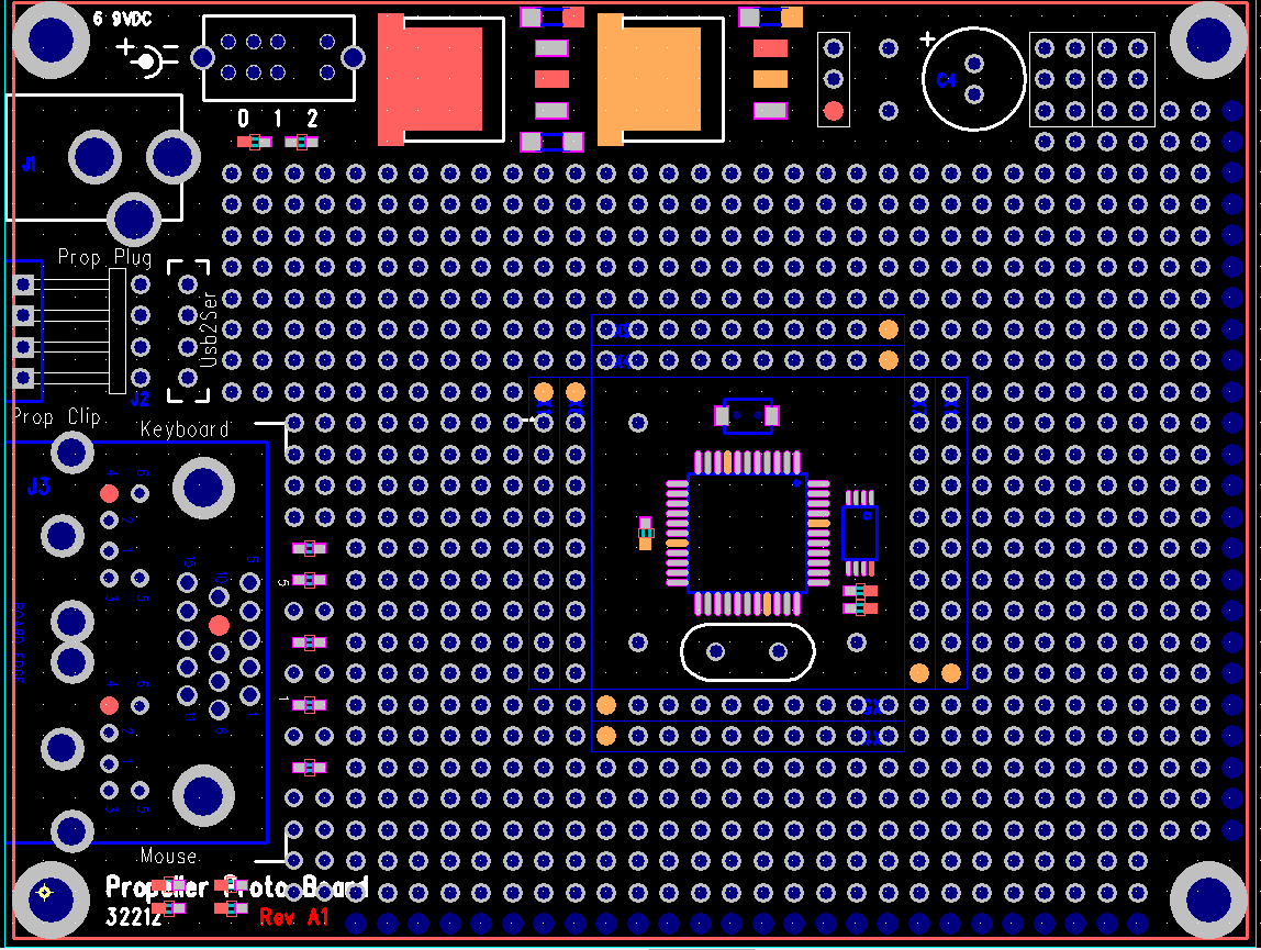
Propeller ProtoBoard Revision 2
The ADC circuitry of the first prototype didn't work as expected (too much noise caused by the way they were routed) as well as a few other nessesary changes. Chip is now involved with the process, so the thing has undergone a pretty major revision. First off, no dedicated ADC circuitry. Instead I have verified that if the Propeller was in a moat and traces kept to a minimum, point to point addition of ADC components works with less noise in the system than the original design, and because the propeller is in an I/O moat any of the pins may be used for ADC. I have included the current image of the board to keep the Parallax community in the loop with this design.
The other major adjustment is with the supply caps, 1000uF was way beyond spec for the regulators and causing unacceptable ripple in the supply. So what we have done instead for the servos is include a dedicated 1000uF cap for the servos with a low resistance 1uH inductor between the supply and the servo cap, this has a 2-fold benefit, first it "encourages" the servos to take power from the cap when changes in servo current draw occur and second it forms an EMI filter to inhibit electrical noise·from the servos from being injected back into the supply.
▔▔▔▔▔▔▔▔▔▔▔▔▔▔▔▔▔▔▔▔▔▔▔▔
Paul Baker
Propeller Applications Engineer
Parallax, Inc.


Comments
RoboGeek
▔▔▔▔▔▔▔▔▔▔▔▔▔▔▔▔▔▔▔▔▔▔▔▔
"I reject your reality and subsitute my own!"
Adam Savage, Mythbusters
www.parallax.com
www.goldmine-elec.com
www.expresspcb.com
www.startrek.com
·
▔▔▔▔▔▔▔▔▔▔▔▔▔▔▔▔▔▔▔▔▔▔▔▔
Paul Baker
Propeller Applications Engineer
Parallax, Inc.
What regulators are you using?
-Phil
▔▔▔▔▔▔▔▔▔▔▔▔▔▔▔▔▔▔▔▔▔▔▔▔
Paul Baker
Propeller Applications Engineer
Parallax, Inc.
Looks cool - i'm intreiged by the stuff with the inductor and the caps, have you a schematic (or partial) you could post.
No worries if not, don't want to spoil the surprise.
James (Javalin)
I was looking over the PPB rev 2. Looks like this layout will still be very usable for my purpose. Will be mounting a 2nd Prop, DIP-40 to the right if sufficient free pads.
I noticed some questionable items.
1. In the lower left mounting hole area is some feature (in yellow) which probably isn't desired.
2. If the power switch is the same as used on SX28 board, the footprint appears to be reversed, 180°.
3. Lower, left it appears some SMD components with silk screening ON them. Or are they on the solder side?
▔▔▔▔▔▔▔▔▔▔▔▔▔▔▔▔▔▔▔▔▔▔▔▔
Harley Shanko
h.a.s. designn
Yes the DIP-40 will still fit
The yellow spot is the program's origin indicator,
The picture a rough draft up Chip and I worked on after the layout engineer left for the day. I will working with the LOE on finalizing layout, which includes silkscreen placement and proper orientation of components such as the switch. The switch will be oriented left-off, middle-cpu powered, right-servos powered.
▔▔▔▔▔▔▔▔▔▔▔▔▔▔▔▔▔▔▔▔▔▔▔▔
Paul Baker
Propeller Applications Engineer
Parallax, Inc.
Thanks Forrest for providing the link to the original thread.
▔▔▔▔▔▔▔▔▔▔▔▔▔▔▔▔▔▔▔▔▔▔▔▔
Paul Baker
Propeller Applications Engineer
Parallax, Inc.
But for $15-$20, thats great.
It looks good, but my biggest question is about the PS/2 and VGA hybrid connector... will this be sold in your store once the board is launched? I love the interface that the Prop can do, but I haven't the foggiest idea where to buy one of those connectors! Thanks.
▔▔▔▔▔▔▔▔▔▔▔▔▔▔▔▔▔▔▔▔▔▔▔▔
Paul Baker
Propeller Applications Engineer
Parallax, Inc.
Thanks - for my powerwheels robot's control system, I have been hung up whether to wait for this board or build one now out of a Basic Stamp and an Atmega8. (The two processor solution is so that the stamp can communicate with the PC and LCD without interrupting PWM to the motors. A Propeller would not have this problem; I could just use separate cogs.) So I think what I will do is go ahead and build the controller for one robot using a Basic Stamp, and then build controllers for the other 3 robots when the Propeller protoboard does come out.
It appears the EEPROM will be surface mount, not socketed DIP? I suppose with only 8 pins, an EEPROM is one of the easier surface mount chips to (de)solder, so I guess it's not such a big hardship to remove it and replace with a bigger EEPROM. That won't be a problem on my motor controller but on my ultra-small portable Propeller computer (currently in planning stage only), I'll need the biggest EEPROM I can get.
I'm glad you decided to just let us add our own ADC - people who don't need it won't have to bother and people who do can choose how many to have.
▔▔▔▔▔▔▔▔▔▔▔▔▔▔▔▔▔▔▔▔▔▔▔▔
Paul Baker
Propeller Applications Engineer
Parallax, Inc.
Regards,
Kova
▔▔▔▔▔▔▔▔▔▔▔▔▔▔▔▔▔▔▔▔▔▔▔▔
Paul Baker
Propeller Applications Engineer
Parallax, Inc.