

I don't get it, the book says 50MHZ
 metron9
Posts: 1,100
metron9
Posts: 1,100
The book says on page 28 use the settings below, the sxkey will generate 50mhz but I cant get it to go more than 4mhz
Heck I thought it was going 50mhz but a loop shows the scope output Tried with resonator The ones I got say 500.L no speed change with those but if I use one of the ones that say 400?450 and another one that says 600?015 they make it go about 500KHZ so I am lost.
CS1_8255 PIN RB.4 OUTPUT
XXX:
high cs1_8255
low cs1_8255
goto xxx
'
' Device Settings
'
DEVICE SX28L, TURBO, STACKX, OSCHS2
IRC_CAL IRC_FAST
FREQ 50_000_000
ID "SXB 1.50"
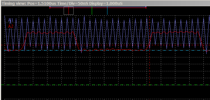
Indeed the OSC2 has a 50mhz clock on it it is taking 11 clock cycles to execute what should be 2 clock cycles
Hmmm...
▔▔▔▔▔▔▔▔▔▔▔▔▔▔▔▔▔▔▔▔▔▔▔▔
Think outside the BOX!
Post Edited (metron9) : 11/3/2006 8:03:01 AM GMT
Heck I thought it was going 50mhz but a loop shows the scope output Tried with resonator The ones I got say 500.L no speed change with those but if I use one of the ones that say 400?450 and another one that says 600?015 they make it go about 500KHZ so I am lost.
CS1_8255 PIN RB.4 OUTPUT
XXX:
high cs1_8255
low cs1_8255
goto xxx
'
' Device Settings
'
DEVICE SX28L, TURBO, STACKX, OSCHS2
IRC_CAL IRC_FAST
FREQ 50_000_000
ID "SXB 1.50"
Indeed the OSC2 has a 50mhz clock on it it is taking 11 clock cycles to execute what should be 2 clock cycles
Hmmm...
▔▔▔▔▔▔▔▔▔▔▔▔▔▔▔▔▔▔▔▔▔▔▔▔
Think outside the BOX!
Post Edited (metron9) : 11/3/2006 8:03:01 AM GMT
529 x 312 - 10K
739 x 352 - 14K
Comments
HIGH and LOW also setup the pin direction. That's why it takes more cycles.
Use:
OUTPUT pin
DO
pin = 1
pin = 0
LOOP
However, you are going to run into read/modify/write problems at high speeds.
Bean.
▔▔▔▔▔▔▔▔▔▔▔▔▔▔▔▔▔▔▔▔▔▔▔▔
Cheap used 4-digit LED display with driver IC·www.hc4led.com
Low power SD Data Logger www.sddatalogger.com
SX-Video Display Modules www.sxvm.com
"People who are willing to trade their freedom for·security deserve neither and will lose both." Benjamin Franklin
·
BTW: I have to do some stuff with my wife this morning so I hope to get back to the 8255 circuit later this morning.
This was just a quick check to see what speed it was operating at as T&E had asked if i used a resonator on the 50mhz test I did on his project. I originally thought I had read the sxkey generates the 50mhz and it does.
So T&E, the sxkey itself generates 50mhz when told to do so by the device settings. The internal 4mhz to 32khz is the internal oscillator on the chip. Generally you do not want to use the internal oscillator for serial communications because it is not precise enough on the ATMEL parts I have worked with. I don't know the stability of the sx internal oscillator. In your project you ace clocking the data out so it doesn't matter.
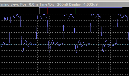
Picture, you can see the first red line on off is 200ns and the second one is actually 2 clock cycles or 40ns starting on the rising edge of the clock signal. I only have a 100mhz scope so measuring 50mhz is the limit due to some guys law I forgot his name, Bean knows.
Curious why the same machine code instruction is genersted by SX/B in both lines 195 and 201, as well as 203, and 209 for the LOW command, anyone know?
 =0000004C       XXX:                             ;XXX:
   194
   195  004C  0586        SETB CS1_8255                  ;high cs1_8255
   196  004D  0CFB        MOV FSR,#__TRISB
        004E  0024
   197  004F  0480        CLRB IND.4
   198  0050  005F        MODE $0F
   199  0051  0200        MOV !RB,IND
        0052  0006
   200  0053  0018        BANK $00
   201  0054  0586        SETB CS1_8255
   202
   203  0055  0486        CLRB CS1_8255                  ;low cs1_8255
   204  0056  0CFB        MOV FSR,#__TRISB
        0057  0024
   205  0058  0480        CLRB IND.4
   206  0059  005F        MODE $0F
   207  005A  0200        MOV !RB,IND
        005B  0006
   208  005C  0018        BANK $00
   209  005D  0486        CLRB CS1_8255
   210
   211  005E  0586        SETB rb.4                      ;rb.4=1
   212
   213  005F  0486        CLRB rb.4                      ;rb.4=0
   214
   215  0060  0010        JMP @xxx                       ;goto xxx
        0061  0A4C
   216
▔▔▔▔▔▔▔▔▔▔▔▔▔▔▔▔▔▔▔▔▔▔▔▔
Think outside the BOX!
The guy's name you're thinking of is Nyquist, and he's famous for the Nyquist theorem. However, the Nyquist theorem has to do with sampling systems (such as analog to digital converters) and has nothing to do with plain old analog systems. Thus, if you have a scope that goes to 100 MHz, then you can read a signal up to 100 MHz.
Here's some info if you want to read more:
www.webopedia.com/TERM/N/Nyquists_Law.html
members.aol.com/ajaynejr/nyquist.htm
Thanks, PeterM
· They were added to prevent glitches on the pin. Let's assume the output latch is set high and you want to do "LOW pin". If you set the direction first, then set the output you will get a high on the pin briefly.
Bean.
▔▔▔▔▔▔▔▔▔▔▔▔▔▔▔▔▔▔▔▔▔▔▔▔
Cheap used 4-digit LED display with driver IC·www.hc4led.com
Low power SD Data Logger www.sddatalogger.com
SX-Video Display Modules www.sxvm.com
"People who are willing to trade their freedom for·security deserve neither and will lose both." Benjamin Franklin
·
50 mhz is 50 million cycles so the transition from high to low is only 10ns and the transition from low to high is 10ns, true it is measureing 50mhz and I see the output on the scope but a 100mhz clock cycle I dont think I could see on a 100mhz scope.
I have an 80mhz oscillator I can plug that in to see.
▔▔▔▔▔▔▔▔▔▔▔▔▔▔▔▔▔▔▔▔▔▔▔▔
Think outside the BOX!
A 100MHz scope may not be able to accuratly display a 100 MHz squarewave signal for example. That is because the squarewave (or anything other than a sinewave) contains harmonics of much higher frequencies inside of it. Most analog designers know that so well they don't bother mentioning it, but us digital people sometimes don't realize it.
For more on Read/Modify/Write problems (which are a seperate issue) see:
http://www.sxlist.com/techref/readmodwrite.htm
For clock information on the SX, see:
http://www.sxlist.com/techref/ubicom/clocks.htm
▔▔▔▔▔▔▔▔▔▔▔▔▔▔▔▔▔▔▔▔▔▔▔▔
---
James Newton, Host of SXList.com
james at sxlist,com 1-619-652-0593 fax:1-208-279-8767
SX FAQ / Code / Tutorials / Documentation:
http://www.sxlist.com Pick faster!
Salient point. As you climb higher and higher with an analog scope, the displayed signal of a square wave develops rounded corners as the system reaches its limit on handling the harmonics. On my 60 MHz scope, a 50 MHz clock looks just like a sinewave, even though I know it's still a square wave.
Metron9,
Still not sure if you have an analog or digital scope. If analog, it's not plotting a point, it's just sweeping the electron beam around on the screen, with all the inherent "infinite" resolution that analog implies. If it's digital, then it is indeed plotting points.
Thanks, PeterM
▔▔▔▔▔▔▔▔▔▔▔▔▔▔▔▔▔▔▔▔▔▔▔▔
Think outside the BOX!