

Reading pins to fast?
 Javalin
Posts: 892
Javalin
Posts: 892
Evening all (well it is in the UK...),
Im running a shift-in routine in ASM doing high-speed reads and writes to an MMC card.· The write routine works perfectly, but the read routine (shift-in) works for about 99% of the time, unless you put some waits in the loop. The waits slow the block read down from about 1-2ms to 15ms.
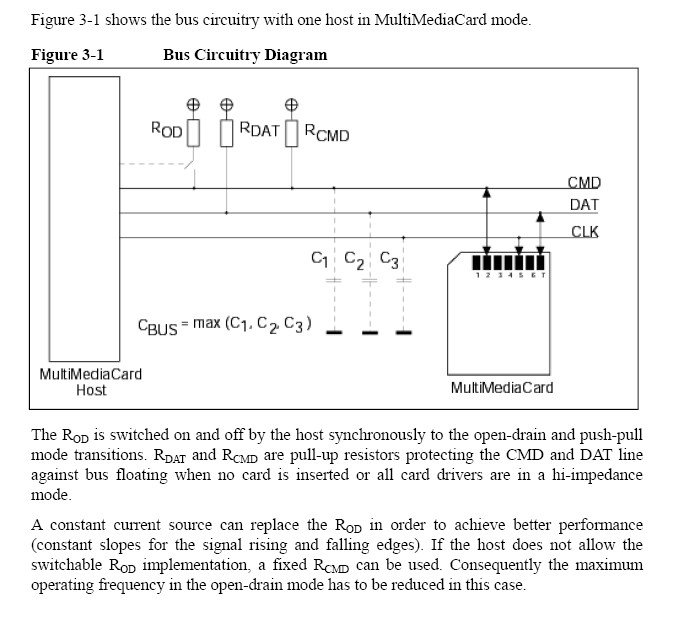
Attached is the diagram for connectivity to the MMC card as following SanDisks (from the MMC spec) documenation.
I have three questions;
· the first is why do they show capacitors to ground on the bus lines?
··the second why use an second "open drain" resistor on the CMD line?
··and the third·is, does this have to do with my issue above - namely the pins are being read faster than the rise/fall time.
Thanks for any help,
James
Im running a shift-in routine in ASM doing high-speed reads and writes to an MMC card.· The write routine works perfectly, but the read routine (shift-in) works for about 99% of the time, unless you put some waits in the loop. The waits slow the block read down from about 1-2ms to 15ms.
Attached is the diagram for connectivity to the MMC card as following SanDisks (from the MMC spec) documenation.
I have three questions;
· the first is why do they show capacitors to ground on the bus lines?
··the second why use an second "open drain" resistor on the CMD line?
··and the third·is, does this have to do with my issue above - namely the pins are being read faster than the rise/fall time.
Thanks for any help,
James
673 x 621 - 87K
Comments
2) The second switchable resistor on the CMD line is intended to speed up the pulling up to +Vcc in case the controller can't supply a lot of current. This isn't an issue with the Propeller.
3) It is odd that the read routines work most of the time and have to slow way way down occasionally. For some reason, the MMC internal controller gets busy doing something. You'd have to post the code and details of the circumstances.
Chip Gracey
Parallax, Inc.
thanks for the response. I've got 10k pull-ups on the CMD,DAT and CS lines - effectivily the dataout,datain and chip select lines. Would a smaller (5k?) resistor work better perhaps?
Mike,
Thanks for the explanation.
James
The MMC command line has two distinct data communication states, open-drain and push-pull, with different electrical characteristics. In non-SPI mode, MMC cards start in "identification mode", where the command line is in an open drain state. In this mode, there may be many cards communicating on the command line at the same time, and the host and the cards negotiate which card the host wants to communicate with. Once a single card is selected, both the card and the host convert the command line to push-pull communication mode for data transfer. The host switches the OD switch to do its part in converting to push-pull mode.
In SPI mode, CS is used to select one of possibly several cards, and the open drain switch is not needed.
The CMD and DAT lines both may be bidirectional and that's why they need pullups. The CS line isn't bidirectional and so doesn't need a pullup.
The document that I have recommends that the pullup resistors on the data and command lines be between 50K and 100K. So maybe you shouldn't go too low.
What is failing when the reads fail? Are you checking for end-of-command status from the card? According to the docs, it is within spec for some reads to take many ms to complete.
David
Interesting. I've been using 10k pull-ups with success running the card with SPIN. I've re-written the code in ASM and the performance has gone from a block read of 150ms to 1-2ms. The read loop runs 99% of the time in 1ms and is successfull.· I get a "0" R1 response on a single block read (cmd17) and then normally the block read token (111111110) then the data block. However when the "failure" occurs I get a "0" R1 then a steady stream of "0's" from the card. I've implemented a retry loop and this also fails unless the spi-Read routine is slowed down. The retry loop de-selects the card (CS high), then re-selects the card (CS low) and resends the cmd17 sequence.
I was experimenting last night following Chip & Mikes suggestions & info - if I put a 1k pull-up on the DAT,CMD,CS lines the rise time is fast enough for me not to drive the CMD line and let the pull-ups drive the line high (similar to i2c). If I use 4.7k's then I have to drive the lines (high/low), if I use 10k the same. I've not noticed a big difference appart from that.
I'll try lower resistors tonight and see.
Interested to hear your thoughts,
James
But I did find that I had to allow as many as 250 attempts to read the card until the $FE appears. When I do that, I do get consistent reliable reads. Does your code repeatedly query the card for the $FE? I thought the zero indicated the card is busy; maybe your code needs to do that.
When I was learning how to access cards, I found it was useful to have a handful of different SD and MMC cards to work with. Sometimes when my friends would upgrade the memory cards in their cameras or MP3 players, they'd give me their old small card free, which I'd use for testing. Have you tried another card to see if it reacts the same way?
David
No I haven't tried it with other types of card - my code is aimed at just MMC. I'll try another make.
The wait loop for the $FE byte upto 511 times ($1FF) and the cmd, r1, read-block token loop can repeat 5 times if no $FE byte is recieved.
I've read that "0" is busy - however in my experience thus far a 255 byte seems to indicate busy.
James